Dental implant fixture

A technique for dental implants and fixtures, applied in the field of improved wedge-locked fixtures, which can solve problems such as difficult operation of fixtures, impossibility of stably supporting dentures, complicated operations of engagement and disengagement, etc.

Inactive Publication Date: 2005-07-13
奈伊公司 +1
View PDF0 Cites 5 Cited by
  • Summary
  • Abstract
  • Description
  • Claims
  • Application Information

AI Technical Summary

Problems solved by technology

[0016] Therefore, as time goes by, the column portion 21 of the abutment 20 may escape, making it impossible to stably support the denture
[0017] Third, during the implantation process, the implant and the alveolar bone may be engaged and disengaged repeatedly, so the operation of engaging and disengaging is complicated
like figure 1 As shown in , because the conventional fixing parts do not have a wrench slot, the operation of the fixing parts is not easy

Method used


Image

  • Dental implant fixture
  • Dental implant fixture
  • Dental implant fixture

Examples


Embodiment Construction

[0031] The present invention will be more fully explained below with reference to the accompanying drawings showing preferred embodiments of the invention.

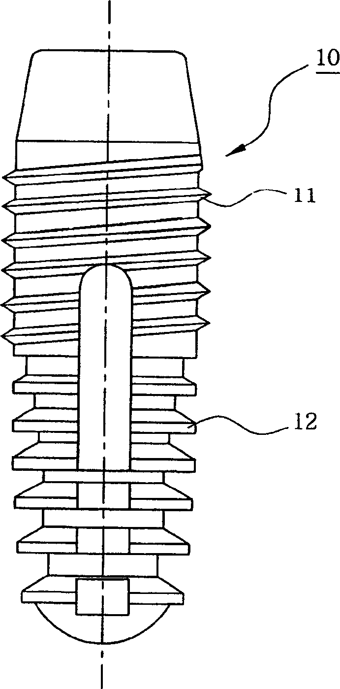
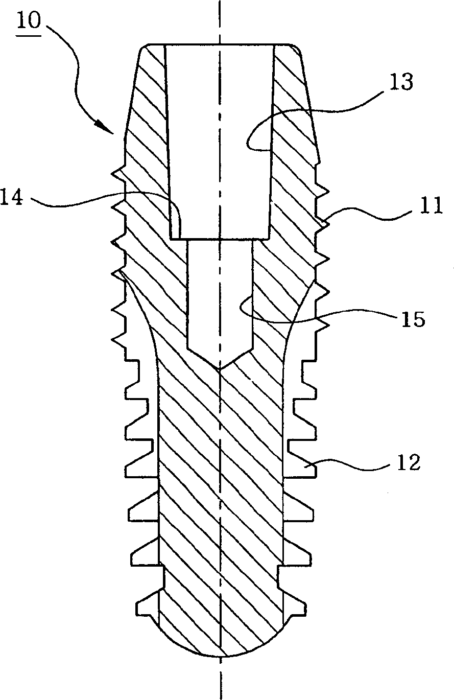
[0032] figure 2 is a front view of a fixture, image 3 is a cross-sectional view of the fixture, Figure 4 and Figure 5 A top view and a cross-sectional view, respectively, of a preferred embodiment of the fastener of the present invention.

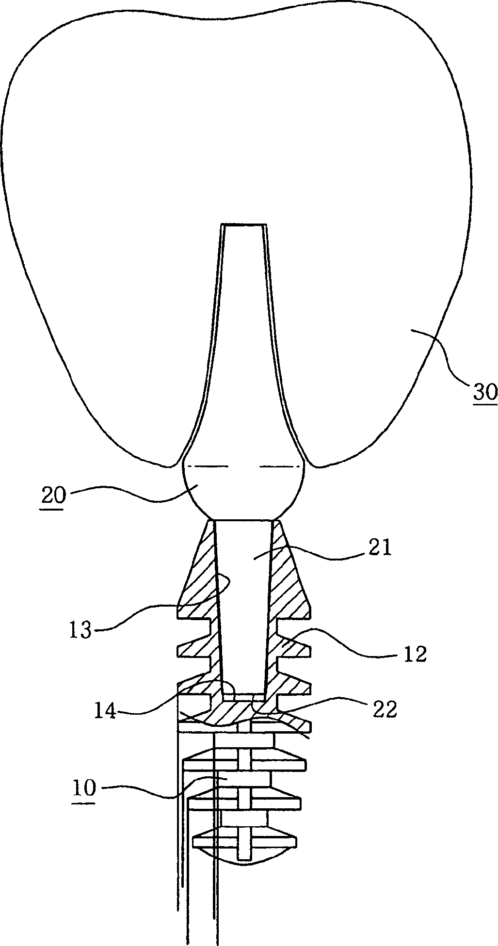
[0033] The dental implant system comprises a fixture 10 having a wedge hole 13 on the upper surface of a cylinder, an abutment 20 having an insert and a crown 30. The peg portion 21 in the hole 13 of the fixture, while the crown 30 is assembled to the upper side of the abutment.

[0034] see now figure 2 , the fixing member 10 has a threaded portion 11 formed in the upper outer cylindrical surface and a plurality of circular plate pins 12 formed in the lower outer cylindrical surface.

[0035] Additionally the threaded portion 11 is provided for easier engagement and disenga...


PUM


Abstract

The present invention relates to a fixture for a dental implant. The fixture for the dental implant adopts a spiral. By forming a threaded portion and a circular pin portion in the outer cylindrical surface of the fixture, the fixture can Easier engagement and disengagement is achieved and the screw is prevented from loosening by the use of a round plate pin, resulting in a stable placement and easier implant surgery. The improved fixed member of the dental implant includes a threaded portion formed in the upper outer cylindrical surface of the fixed member for achieving a relatively easy and convenient engagement and disengagement; and in the lower outer cylindrical surface of the fixed member Multiple round plate pins are provided in to enhance stability as the alveolar bone develops, and the hole has a deeper space at the bottom to prevent air compression issues when assembling the column portion of the abutment. .

Description

technical field [0001] The invention relates to a fixing part of a dental implant. More particularly, the present invention relates to an improved wedge lock fastener having a threaded portion and a circular plate pin portion in the outer cylindrical surface. And a deep space is additionally formed in the inner bottom of the hole of the post portion in which the abutment is inserted, thereby preventing loosening due to compressed air. In addition the deeper space is formed in a wrench slot, allowing for an easier implant surgery. Background technique [0002] A dental implant system is an abutment attached in a fixture inserted into the alveolar bone and a crown covering the abutment. Each implant is anchored independently, and the anchored implants are not supported by adjacent teeth. Therefore, there is no need to destroy natural teeth in order to support damaged teeth. According to a condition, it is possible to stably fix a denture. Implants have a long life and loo...

Claims


Application Information

Patent Timeline
Patent Type & Authority Applications(China)
IPC IPC(8): A61C8/00
CPCA61C8/0018A61C8/0022A61C8/0071E01D21/00E01D19/02
Inventor 张相健
Owner 奈伊公司
Why Eureka
Try Eureka