Switch device

A switch device and switch technology, which is applied in the direction of electric switches, components of flip switches/rocker switches, electrical components, etc., can solve problems such as complex processing

Inactive Publication Date: 2007-01-17
ALPS ALPINE CO LTD
View PDF1 Cites 3 Cited by
  • Summary
  • Abstract
  • Description
  • Claims
  • Application Information

AI Technical Summary

Problems solved by technology

Therefore, there is a problem that the processing of the actuator 23 becomes complicated.

Method used


Image

  • Switch device
  • Switch device
  • Switch device

Examples


Embodiment Construction

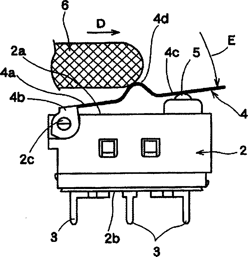
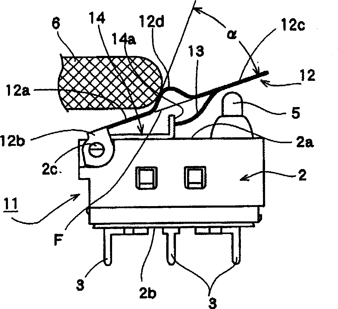
[0047] Next, first and second embodiments of the switchgear according to the present invention will be described based on the drawings. figure 1 It is a side view before the switch operation of the first embodiment of the present invention, figure 2 is description figure 1 side view of the switch operation, image 3 It is a side view before switch operation of the second embodiment of the present invention, Figure 4 , Figure 5 is description figure 1 Side view of the switch operation.

[0048] First, the switch device 1 of the first embodiment, such as figure 1 As shown, a housing 2 formed of an insulating material such as a resin material and having a switching circuit (not shown) formed therein is arranged. This housing 2 has one side wall 2a formed on the upper part in the drawing, and the other side wall 2b formed on the lower part in the drawing.

[0049] From the other side wall 2b of the frame body 2, a plurality of terminal portions 3 connected to an inte...


PUM


Abstract

The invention provides a switching device using an actuator capable of accelerating a response speed at the time of switching operation with a working member with a small movement volume, with a simple structure and easy to manufacture. An actuator (4) of a switch device (1) is formed with a protrusion (4d) which is a pressing portion which an external action member (6) can operate by pressing, such that moving the action member (6) in one direction parallel to one side wall (2a) of a casing (2) in a state with a supporting portion (4b) being rotatably supported by a turning supporting portion (2c) of the casing (2) causes the protrusion (4d) to be pressed in the direction toward the one side wall (2a) such that the actuator (4) can turn on the supporting portion (4b) as a point of support, wherein the amount of turning of the protrusion (4d) at the time of turning the actuator (4) downwards by moving the action member (6) in the one direction parallel to the one side wall (2a) is greater than the amount of movement of the action member in the one direction.

Description

technical field [0001] The present invention relates to a switch device, and relates to a switch device for switching a switching circuit by moving and operating an external operating member in one direction and rotating an actuator in a direction perpendicular to the moving direction of the operating member. Background technique [0002] Based on patent document 1 Figure 6 , Figure 7 A conventional switch device will be described. A conventional switch device 20 is provided with a housing 21 and a predetermined switching circuit (not shown) is formed inside the housing 21 . A plurality of terminal portions 22 connected to an internal switching circuit are formed extending from the lower side of the housing 21 in the figure. [0003] In addition, the actuator 23 is made of a metal plate, and the mounting leg 24 on the left side in the figure is fixed to the frame body 21 by press fitting or the like, and is integrated with the frame body 21 . [0004] The mounting leg po...

Claims


Application Information

Patent Timeline
IPC IPC(8): H01H23/16
CPCH01H21/282H01H21/24H01H13/186
Inventor 芳贺修
Owner ALPS ALPINE CO LTD
Why Eureka
Try Eureka