Lighting apparatus and vehicular lamp comprising the same

a technology of lighting apparatus and vehicular lamp, which is applied in the direction of lighting and heating apparatus, semiconductor devices for light sources, instruments, etc., can solve the problems of difficult to meet ameca standards, difficult to implement lighting units in slimming structures, and difficult to create designs. , to achieve the effect of uniform light, slimming structure, and reducing the thickness of the entire lighting devi

Active Publication Date: 2019-05-28
LG INNOTEK CO LTD
View PDF30 Cites 1 Cited by
  • Summary
  • Abstract
  • Description
  • Claims
  • Application Information

AI Technical Summary

Benefits of technology

[0010]According to the present invention, the lighting device has a structure in which the diffusion member is buried in the light guide member, so that the uniformity of light can be ensured and the thickness of the entire lighting device can be decreased.
[0011]Also, when the lighting device is applied to a vehicle lamp, the vehicle lamp can be implemented as a vehicle lamp that can satisfy AMECA Standard in North America, create various designs, and have a sliming structure.
[0012]Further, the shielding module having a bracket structure, which supports the light source module, is formed in a structure shielding one region above the light source module, and enables light emitted from the light source to be reflected from a shielding region and condensed into the diffusion member, thereby increasing the light intensity and luminance of a light emitting part.
[0013]In particular, the shielding module is implemented in a structure having a bending part formed by bending an upper end of the shielding module, and luminance can be adjusted based on a bending angle of the bending part.
[0014]In addition, a lens member is provided between the shielding module and the light guide member, so that it is possible to ensure variety in design of the lighting device and to simultaneously enhance light efficiency through a non-air-gap structure in which spacing parts between components are removed.

Problems solved by technology

However, when the surface light source is to be mounted in various places such as a vehicle lamp, it is not easy to create a design for mounting the surface light source, and it is difficult to satisfy AMECA Standard in North America for the purpose of export overseas.
In addition, due to the limit of the lighting unit to have a certain standard and configuration, it is difficult to implement the lighting unit in a slimming structure while ensuring a desired uniformity of light in a limited place.

Method used


Image

  • Lighting apparatus and vehicular lamp comprising the same
  • Lighting apparatus and vehicular lamp comprising the same

Examples


Embodiment Construction

[0017]Hereinafter, constitutions and operations according to the present invention will be described in detail with reference to the accompanying drawings. Like reference numerals denote like elements, and a repeated description will be omitted. It will be understood that, although the terms “first,”“second,” and the like may be used herein to describe various elements, these elements should not be limited by these terms. These terms are only used to distinguish one element from another.

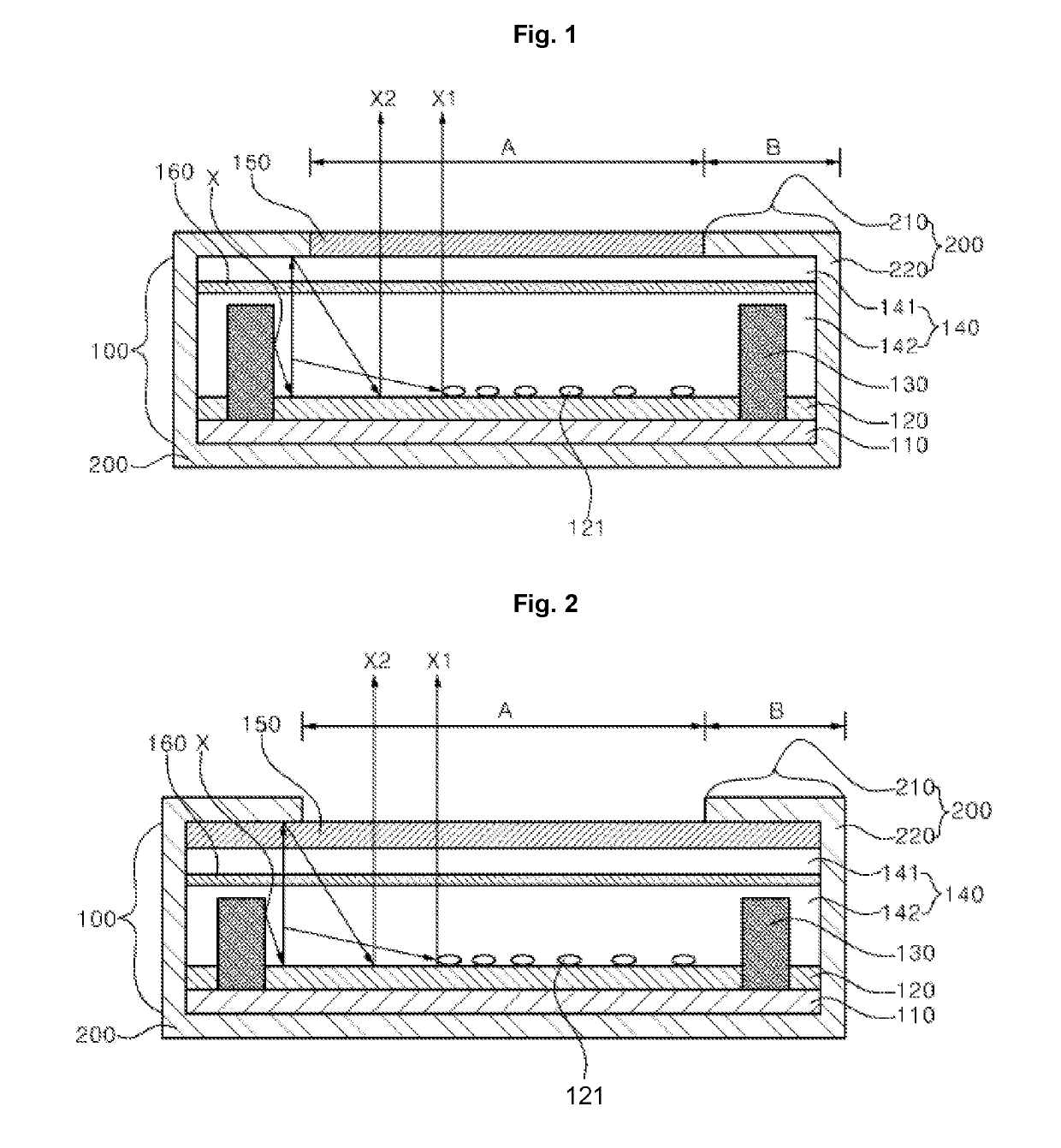
[0018]FIG. 1 is a sectional conceptual view showing main parts of a lighting device according to an embodiment of the present invention.

[0019]Referring to FIG. 1, the lighting device according to the embodiment of the present disclosure may include a light source module 100 including at least one light source 130 and a light guide member 140 burying the light source 130, a shielding module 200 accommodating the light source module 100 therein, the shielding module 200 having an opening region A and a...


PUM


Abstract

In the present invention, there is provided a lighting device including: a light source module including at least one light source and a light guide member that buries the light source; a shielding module accommodating the light source module therein, the shielding module having an opening region and a shielding region, which are provided above the light guide member; and a diffusion member disposed in the light guide member.

Description

CROSS-REFERENCE TO RELATED PATENT APPLICATIONS[0001]This application is a U.S. National Stage Application under 35 U.S.C. § 371 of PCT Application No. PCT / KR2015 / 011103, filed Oct. 20, 2015, which claims priority to Korean Patent Application No. 10-2014-0143430, filed Oct. 22, 2014, whose entire disclosures are hereby incorporated by reference.TECHNICAL FIELD[0002]The present invention relates to a lighting device and a vehicle lamp including the same.BACKGROUND ART[0003]A lighting unit in which various light sources used in electronic devices are utilized has been implemented in such a manner as to increase light efficiency by utilizing an appropriate light source according to each property of the electronic devices.[0004]The lighting unit used in the electronic devices has recently been variously applied to a backlight unit applied to a flat display, an indoor light used in indoor environments, a headlight, a fog light, a backlight, a sidelight, a license plate light, a taillight,...

Claims


Application Information

Patent Timeline
Patent Type & Authority Patents(United States)
IPC IPC(8): B60Q1/00F21S43/40F21S43/30F21S43/249F21S43/245F21S43/239F21S43/00F21S43/14F21V8/00B60Q1/02F21S41/37F21S41/40F21S41/30F21S41/24
CPCB60Q1/02F21S43/00F21S43/14F21S43/239F21S43/245F21S43/249F21S43/30F21S43/40G02B6/0021G02B6/0025G02B6/0028G02B6/0041G02B6/0051G02B6/0055G02B6/0076B60Q1/00G02B6/0091F21S41/24F21S41/30F21S41/37F21S41/40G02B6/0065G02B6/0068F21S41/141F21S43/26F21S41/285F21K9/61F21K9/69F21V7/22F21W2107/00F21Y2101/00
Inventor CHAE, HYUN HEEPARK, KWANG HOLEE, BYOUNG EON
Owner LG INNOTEK CO LTD
Why Eureka
Try Eureka