Check patentability & draft patents in minutes with Patsnap Eureka AI!

Optical measuring device and electronic device including the same

Active Publication Date: 2019-06-04
SAMSUNG ELECTRONICS CO LTD
View PDF19 Cites 0 Cited by
  • Summary
  • Abstract
  • Description
  • Claims
  • Application Information

AI Technical Summary

Benefits of technology

The patent describes an optical measuring device that can adjust the length of the optical path by using a light beam path adjuster to change the progress path of light emitted from a light source. The device includes a controller that compares the effective beam path length of the reflected light with a target beam path length and adjusts the refractive angle of the light beam path adjuster accordingly. This allows for precise measurement of objects. The device is simple and compact in size, making it easy to use in various electronic devices.

Problems solved by technology

Also, the exemplary embodiments are not required to overcome the disadvantages described above, and may not overcome any of the problems described above.

Method used


Image

  • Optical measuring device and electronic device including the same
  • Optical measuring device and electronic device including the same
  • Optical measuring device and electronic device including the same

Examples


Embodiment Construction

[0024]Exemplary embodiments are described in greater detail below with reference to the accompanying drawings.

[0025]In the following description and the drawings, like drawing reference numerals are used for like elements, even in different drawings. The matters defined in the description, such as detailed construction and elements, are provided to assist in a comprehensive understanding of the exemplary embodiments. However, it is apparent that the exemplary embodiments can be practiced without those specifically defined matters. Also, well-known functions or constructions are not described in detail since they would obscure the description with unnecessary detail.

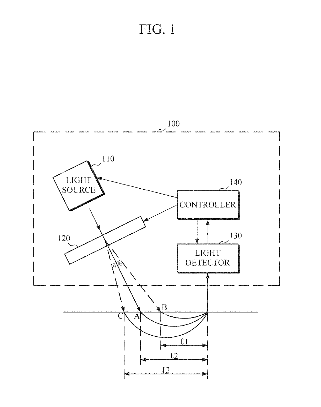
[0026]FIG. 1 is a block diagram showing a configuration of an optical measuring device according to an exemplary embodiment. Referring to FIG. 1, an optical measuring device 100 includes a light source 110, a light beam path adjuster 120, a light detector 130 and a controller 140.

[0027]The light source 110 emits measuring...


PUM

PropertyMeasurementUnit
refractive angleaaaaaaaaaa
thicknessaaaaaaaaaa

Abstract

An optical measuring device including a light source, a light beam path adjuster, a light detector and a controller is provided. The light source may emit light toward an object in a predetermined progress direction. The light beam path adjuster may be disposed between the light source and the object and may change a progress path of the light emitted from the light source. The light detector may receive the light that is reflected from the object after passing through the light beam path adjuster. The controller may compare a first effective beam path length of the reflected light that the light detector receives with a predetermined target beam path length and control a refractive angle of the light beam path adjuster based on a beam path length difference between the first effective beam path length and the predetermined target beam path length.

Description

CROSS-REFERENCE TO RELATED APPLICATION[0001]This application claims priority from Korean Patent Application No. 10-2015-0163602, filed on Nov. 20, 2015 in the Korean Intellectual Property Office, the disclosure of which is incorporated herein by reference in its entirety.BACKGROUND[0002]1. Field[0003]Apparatuses and methods consistent with exemplary embodiments relate to analyzing body component by using an optical measuring device.[0004]2. Description of Related Art[0005]An optical measurement method using infrared light or near infrared ray (NIR) may be used to measure a certain body component, such as blood sugar. By using the optical measurement method, a component in an object may be detected and / or analyzed in a non-invasive manner, or a diagnosis can be performed through the detection and / or the analysis. The optical measurement method includes a spectrum analysis method of detecting and / or analyzing a specific component by analyzing light absorptivity in a particular wavelen...

Claims


Application Information

Patent Timeline
Patent Type & Authority Patents(United States)
IPC IPC(8): A61B5/00A61B5/145G01N33/49A61B5/1455
CPCA61B5/0059A61B5/1455A61B5/14532A61B5/443A61B5/6803A61B5/7278A61B5/74G01N33/49A61B5/681A61B2562/0242
Inventor LEE, SEUNG JUNKIM, DONG HOBAE, JUNG MOKSHIN, EUI SEOKLEE, WOO CHANG
Owner SAMSUNG ELECTRONICS CO LTD
Features
  • R&D
  • Intellectual Property
  • Life Sciences
  • Materials
  • Tech Scout
  • Unparalleled Data Quality
  • Higher Quality Content
  • 60% Fewer Hallucinations
Learn More