
Aircraft wing comprising a controllable-attack wing tip

a technology of controllable attack and wing tip, which is applied in the direction of airflow influencers, aircraft stabilisation, influencers by generating vortices, etc., can solve the problems of complicated design of wings that integrate this type of solution, and achieve the effect of improving the overall performance of wings

Active Publication Date: 2019-06-25
AIRBUS OPERATIONS (SAS)
View PDF11 Cites 0 Cited by
  • Summary
  • Abstract
  • Description
  • Claims
  • Application Information

AI Technical Summary

Benefits of technology

The invention provides a degree of freedom in attack between the wing tip and the main part of the wing, which improves the overall performance of the wing. This is because controlling the wing tip in attack allows for optimal induced drag based on flight altitude and mass of the aircraft. In addition, untwisting the wings by orienting the wing tip reduces wake production, allowing for more frequent landings and improving the aircraft's braking capability during landing.

Problems solved by technology

However, most of the solutions introduced by the prior art remain open to improvement, notably in that they are liable to generate unwanted drag during certain flight phases and in that they make the design of the wings that integrate this type of solution more complicated.

Method used


Image

  • Aircraft wing comprising a controllable-attack wing tip
  • Aircraft wing comprising a controllable-attack wing tip
  • Aircraft wing comprising a controllable-attack wing tip

Examples


Embodiment Construction

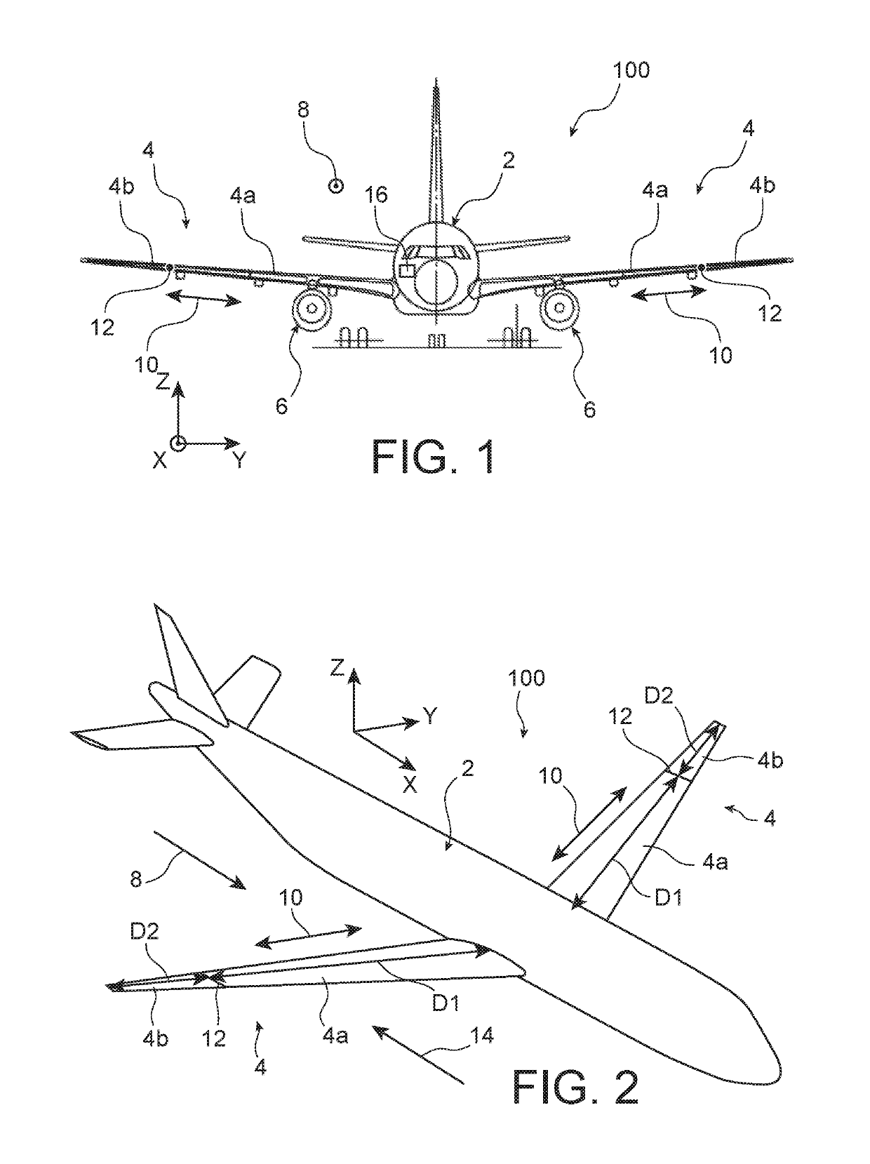
[0026]Referring first of all to FIGS. 1 and 2, there is represented an aircraft 1 in accordance with the invention including a fuselage 2, two wings 4, and a propulsion unit 6 fixed under each wing 4. One of the particular features of the invention resides in the optimized design of each of the two wings 4, which will be described in detail hereinafter.

[0027]Throughout the following description, by convention, the direction X corresponds to the longitudinal direction of the aircraft, the direction Y corresponds to the direction oriented transversely, while the direction Z corresponds to the vertical direction or height. These three directions X, Y and Z are mutually orthogonal and form a direct trihedron. Also, the terms “front” and “rear” are to be considered relative to a direction of forward movement of the aircraft, diagrammatically represented by the arrow 8.

[0028]The two wings 4 being of symmetrical design with respect to a vertical median plane of the aircraft, only one of th...


PUM


Abstract

An aircraft wing, including a main part and a wing tip mounted mobile in attack relative to the main part.

Description

CROSS-REFERENCES TO RELATED APPLICATIONS[0001]This application claims the benefit of the French patent application No. 1555494 filed on Jun. 16, 2015, the entire disclosures of which are incorporated herein by way of reference.BACKGROUND OF THE INVENTION[0002]The present invention relates to the field of aircraft wings.[0003]Aircraft wings have already been the subject of numerous developments that aim to improve their overall performance. This refers, for example, to the installation of flaps or analogous elements with the aim of addressing specific requirements as a function of the various flight phases of the aircraft.[0004]However, most of the solutions introduced by the prior art remain open to improvement, notably in that they are liable to generate unwanted drag during certain flight phases and in that they make the design of the wings that integrate this type of solution more complicated. There is, therefore, a requirement to optimize the design of existing wings and to addr...

Claims


Application Information

Patent Timeline
Patent Type & Authority Patents(United States)
IPC IPC(8): B64C3/42B64C3/38B64C5/10B64C23/06
CPCB64C23/072B64C3/38B64C3/42B64C5/10B64C3/385Y02T50/164Y02T50/10
Inventor CAZALS, OLIVIERDRUOT, THIERRY
Owner AIRBUS OPERATIONS (SAS)
Learn More