Swivel device for rotating a bowl

Active Publication Date: 2020-05-12
PRUITT TOOL & SUPPLY
View PDF2 Cites 0 Cited by
  • Summary
  • Abstract
  • Description
  • Claims
  • Application Information

AI Technical Summary

Benefits of technology

[0023]Another object of the present invention is to create a safer work environment for rig personnel.
[0024]Another object of the present invention is to avoid unnecessar

Problems solved by technology

The flowline is placed in a fixed position such that adjusti

Method used


Image

  • Swivel device for rotating a bowl
  • Swivel device for rotating a bowl
  • Swivel device for rotating a bowl

Examples


Embodiment Construction

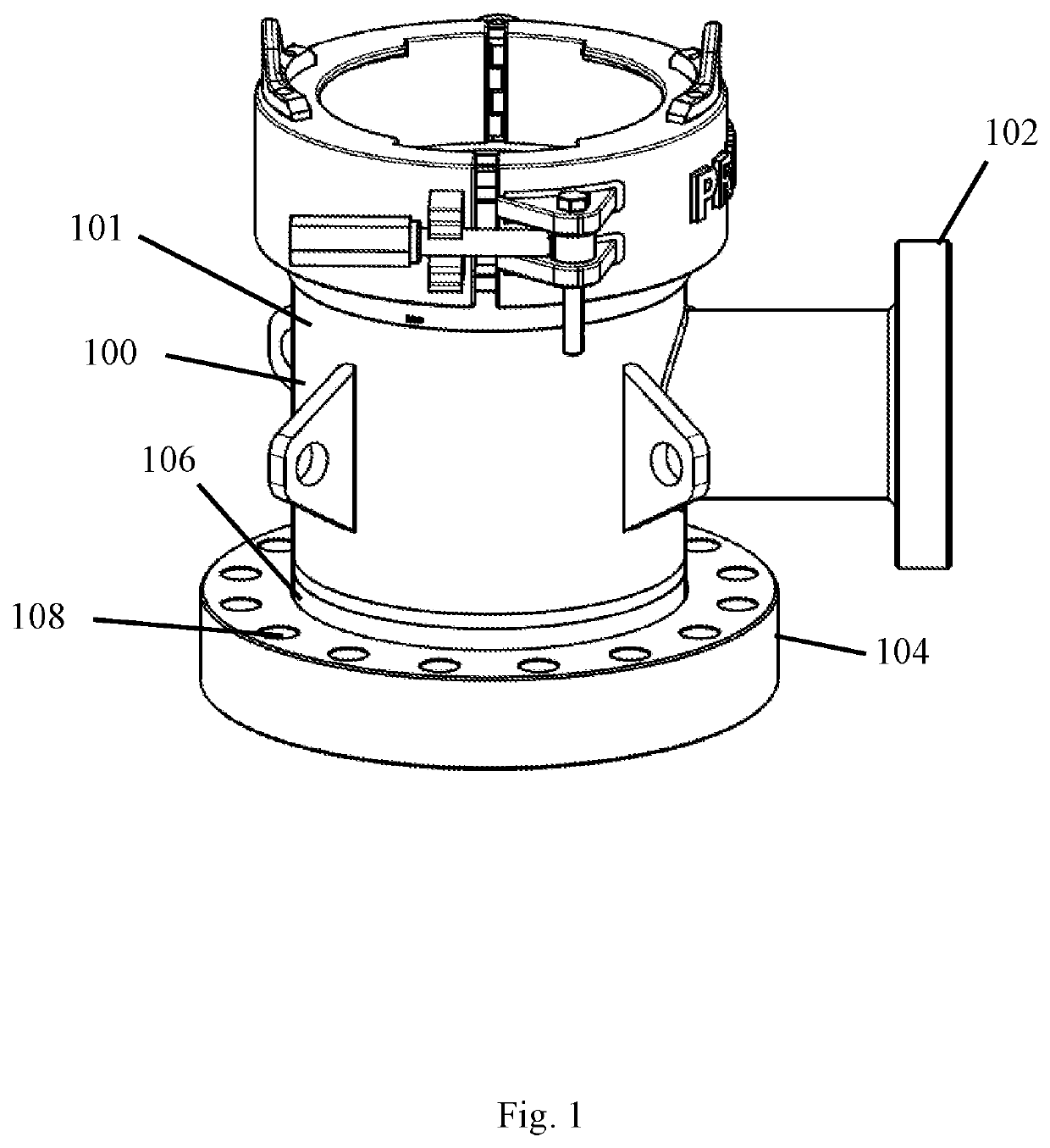
[0040]The swivel device 100 of one embodiment shown in FIG. 1 is implemented as a component of the bowl 101 as shown in FIG. 1 or as a separator device 118 as shown in FIG. 8. The swivel device 100, 118 enables adjustment of the bowl 101 to align the outlet 102 with the flowline.

[0041]The swivel device 100, 118 attaches to the stack (not pictured). The swivel device 100 of one embodiment is a component of the bowl. As a component of the bowl 101, the swivel device 100 eliminates the need for multiple attachments. Such an embodiment also reduces the amount of equipment required at the drilling operation.

[0042]In another embodiment, the swivel device 118 provides a neck 126 that raises the bowl (not pictured) above the annular as shown in FIG. 8. Both swivel devices 100, 118 secure to the stack. A bottom shoulder, such as a flange, secures to the stack. A neck is secured within the shoulder to allow the neck to rotate. Such rotation enables fine adjustment of the outlet 102 of the bow...


PUM


Abstract

The swivel device attaches to a bowl or is implemented as a component of the bowl. The swivel device enables adjustment of the bowl to align the outlet with the flowline. A flange of the swivel device includes multiple fastener apertures for securing the flange to the stack. The swivel device secures the bowl to the stack while allowing rotation of the bowl. Rotation of the bowl adjusts the positioning of the outlet to align the outlet with the flowline for connecting the outlet to the flowline.

Description

CROSS-REFERENCE TO RELATED APPLICATIONS[0001]This application is a continuation in part of U.S. patent application Ser. No. 15 / 464,021 filed on Mar. 20, 2017 entitled SWIVEL DEVICE FOR ROTATING A BOWL.STATEMENT REGARDING FEDERALLY SPONSORED RESEARCH OR DEVELOPMENT[0002]Not Applicable.REFERENCE TO A MICROFICHE APPENDIX[0003]Not Applicable.RESERVATION OF RIGHTS[0004]A portion of the disclosure of this patent document contains material which is subject to intellectual property rights such as but not limited to copyright, trademark, and / or trade dress protection. The owner has no objection to the facsimile reproduction by anyone of the patent document or the patent disclosure as it appears in the Patent and Trademark Office patent files or records but otherwise reserves all rights whatsoever.BACKGROUND OF THE INVENTION1. Field of the Invention[0005]The present invention relates to securing drilling equipment while allowing for rotation and swiveling of the equipment for proper installat...

Claims


Application Information

Patent Timeline
IPC IPC(8): E21B33/08E21B17/16E21B33/04E21B17/02
CPCE21B33/0415E21B17/16E21B33/085E21B17/02E21B17/05E21B33/03E21B33/04
Inventor PRUITT, GRANTBRAUN, CRIS
Owner PRUITT TOOL & SUPPLY
Why Eureka
Try Eureka