Drive device for illuminating device, illumination device, lighting system and method for controlling the lighting system

a technology of driving device and illumination device, which is applied in the direction of electric lighting source, electroluminescent light source, and use of semiconductors. it can solve the problems that the led light source is often not applicable to the ecg dedicated to the fluorescent light source, and achieve the effect of increasing the conduction time of the switch unit, and reducing the electric output signal

Active Publication Date: 2020-06-30
LEDVANCE GMBH
View PDF11 Cites 0 Cited by
  • Summary
  • Abstract
  • Description
  • Claims
  • Application Information

AI Technical Summary

Benefits of technology

[0007]Preferably, the control unit increases the conduction time of the switch unit so as to reduce the electric output signal for the illuminating load, and the control unit decreases the conduction time of the switch unit so as to increase the electric output signal for the illuminating load.
[0012]In the present invention, the control unit of the drive device especially advantageously forms a positive feedback control mode so as to change the output situation of the power adapter device located upstream of the drive device in a situation that an output signal fed back from the illuminating load is sensed, thereby the output signal for the illuminating device subsequently can be stabilized in a predetermined range. Besides, this drive device can correspondingly change the impedance of the drive device particularly according to the properties of the ECG electronic ballast such that the LED load is better adapted to the ECG electronic ballast.
[0014]According to a preferred solution of the present invention, the control unit is configured to regulate the drive device in such a manner that the power adapter device increases its output voltage when the electric output signal measured from the illuminating load is lower than a predetermined value, and the control unit is configured to regulate the drive device in such a manner that the power adapter device decreases the output voltage when the electric output signal measured from the illuminating load is higher than the predetermined value. The drive device according to the present invention can initiatively sense the electric output signal from the illuminating load, and, when determining whether or not it is within a predetermined range, change the output situation of the power adapter device so as to realize the purpose of stabilizing the electric output signal for the illuminating device.
[0017]Advantageously for the solution of the present invention, the control unit of the inventive drive device increases the conduction time of the switch unit so as to reduce the electric output signal for the illuminating load, and the control unit decreases the conduction time of the switch unit so as to enlarge the electric output signal for the illuminating load. This results in said positive feedback control mode. The control compensation preferably provides a proportional or a proportional-integrating characteristic, saying that the feed-back path comprises at least a resistor or a series-connection out of a resistor and a capacitor.
[0024]Preferably for the solution of the present invention, the drive device is configured as a boost circuit. In a situation that the ECG electronic ballast follows an increase of the impedance of the drive device, the constant current output of the electronic ballast can have an increased voltage output, and the boost circuit therefore can receive more energy, thereby the output power of the boost circuit is increased, and further the current of the LED load is increased. When the LED current is matched and is stable at a certain predetermined value, the output of the boost circuit will be stable at a certain value, and the duty cycle for conduction time of the switch unit also will be stable at a certain value.

Problems solved by technology

In the above improvement on the T8 lamp, the ECG electronic ballast for driving the fluorescent lamp may not be removed from the luminaire because the latter one remains installed, and thus furthermore the ECG type keeps hidden, but some ECGs dedicated to the fluorescent light source often are not applicable to the LED light source because of the problem that the LED light source usually may not be compatible with different ECG types.

Method used


Image

  • Drive device for illuminating device, illumination device, lighting system and method for controlling the lighting system
  • Drive device for illuminating device, illumination device, lighting system and method for controlling the lighting system

Examples


Embodiment Construction

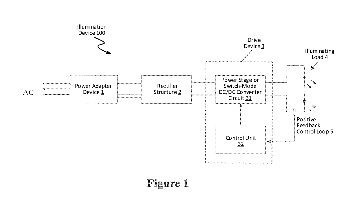
[0035]As shown in FIG. 1, an illuminating device 100 according to the present invention is configured to comprise an ECG electronic ballast connected and adapted to a power supply, a rectifier structure 2 located downstream of the ECG electronic ballast as a power adapter device 1, a drive device 3 according to the present invention connected downstream of the rectifier structure 2, and a light source supplied by the drive device 3 in a controlled manner. In the present invention, the power supply for the ECG electronic ballast preferably can be an alternating current mains just as shown in the figure. Besides, in the present invention, the ECG electronic ballast is preferably configured to output a constant current electric signal, and the light source according to the present invention is preferably configured as an LED light source.

[0036]The drive device 3 according to the present invention is preferably configured to comprise a control unit 32 and a power stage 31 connected to t...


PUM


Abstract

The present invention relates to a drive device for an illuminating load, an illumination device, a lighting system and a method for controlling the lighting system, wherein the drive device is connected between the illuminating load and a power adapter device for power supply, wherein the drive device comprises a control unit, wherein the control unit is configured to adjust the impedance of the drive device according to an electric output signal measured from the illuminating load so as to accordingly adjust the output voltage of the power adapter device and thereby to adjust the electric output signal for the illuminating load.

Description

TECHNICAL FIELD[0001]The present invention relates to a drive device for an illumination device, an illumination device, a lighting system and a method for controlling the lighting system, wherein the illumination device particularly comprises a LED illuminating load and is adapted to use an ECG electronic ballast as further part of said lighting system.BACKGROUND ART[0002]In the current illuminating devices in common use, the LED illuminating devices are widely used due to their performances of energy saving and high efficiency to replace the illuminating devices such as filament lamps or fluorescent lamps. For example, as the LED technology is widely used, the light source of most of the T8 luminaires is changed to the LED light source using the LED technology, and the suitable LED driver is correspondingly used, such that the fluorescent light source is removed while the tube sockets of the T8 lamp are retained in the respective luminaire. In this way, the manufactured light sour...

Claims


Application Information

Patent Timeline
Patent Type & Authority Patents(United States)
IPC IPC(8): H05B33/08H05B45/37H05B45/50H05B45/00H05B44/00
CPCH05B45/00H05B45/50H05B45/37Y02B20/383H05B45/38Y02B20/30H05B45/345H05B45/305H05B45/3578H05B45/325H05B45/3725
Inventor LIN, DAXINYANG, XUSHENG
Owner LEDVANCE GMBH
Why Eureka
Try Eureka