

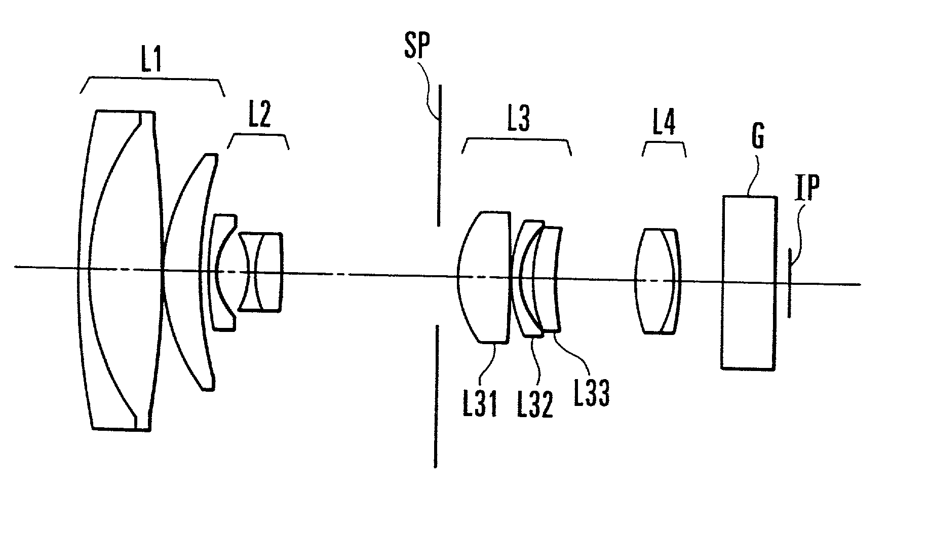
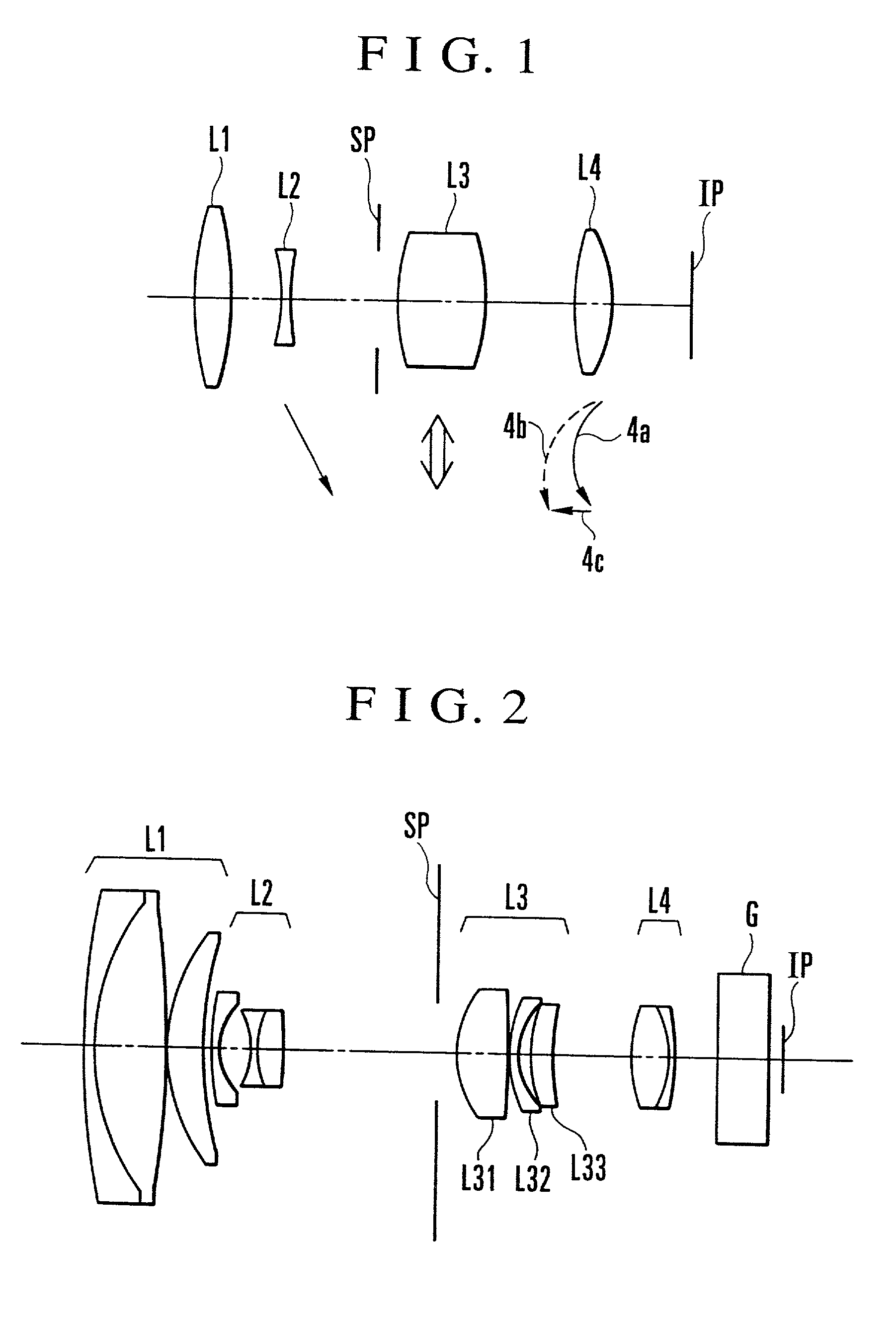
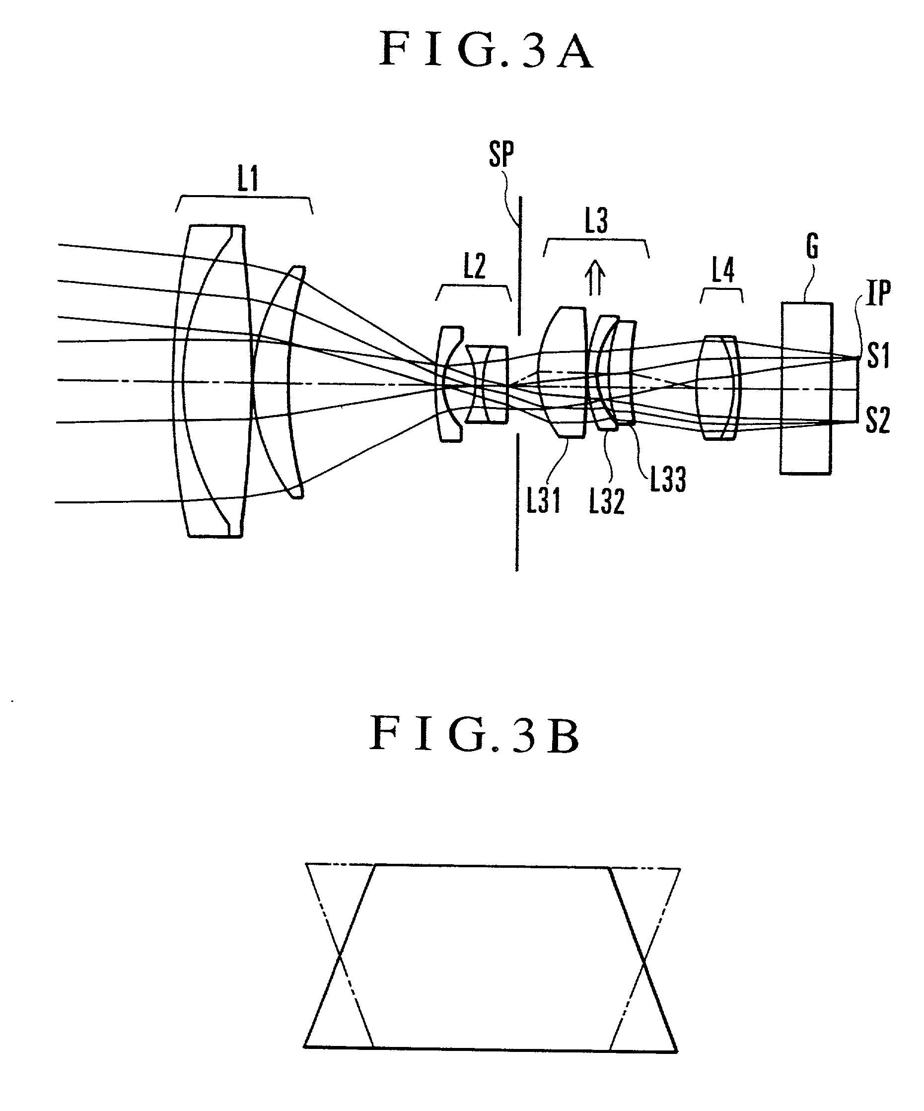
Variable magnification optical system having image stabilizing function
a technology of magnification optical system and image stabilizing function, which is applied in the direction of optics, optical elements, instruments, etc., can solve the problems of image shake, complex structure of the operating mechanism for moving the movable lens unit, and large size of the entire apparatus
- Summary
- Abstract
- Description
- Claims
- Application Information
AI Technical Summary
Problems solved by technology
Method used
Image

Examples
numerical example 3
[0167] Numerical Example 3
[0168] f=1-9.76 Fno=1.85-2.44 2.omega.=60.5.degree.-6.8.degree.
[0169] R 1=13.534 D 1=0.18 N 1=1.84666 .upsilon. 1=23.8
[0170] R 2=4.112 D 2=1.21 N 2=1.71299 .upsilon. 2=53.8
[0171] R 3=-16.831 D 3=0.04
[0172] R 4=3.173 D 4=0.60 N 3=1.77249 .upsilon. 3=49.6
[0173] R 5=6.780 D 5=Variable
[0174] R 6=4.370 D 6=0.14 N 4=1.83480 .upsilon. 4=42.7
[0175] R 7=1.013 D 7=0.57
[0176] R 8=-1.234 D 8=0.12 N 5=1.69679 .upsilon. 5=55.5
[0177] R 9=1.525 D 9=0.44 N 6=1.84666 .upsilon. 6=23.8
[0178] R10=-11.259 D10=Variable
[0179] R11=Stop D11=0.33
[0180] *R12=1.649 D12=0.76 N 7=1.67790 .upsilon. 7=55.3
[0181] R13=-13.084 D13=0.04
[0182] R14=2.280 D14=0.14 N 8=1.84666 .upsilon. 8=23.8
[0183] *R15=1.243 D15=0.18
[0184] R16=2.016 D16=0.40 N 9=1.58312 .upsilon. 9=59.4
[0185] R17=4.117 D17=Variable
[0186] *R18=2.391 D18=0.64 N10=1.58913 .upsilon.10=61.2
[0187] R19=-1.763 D19=0.12 N11=1.84666 .upsilon.11=23.8
[0188] R20=-3.732 D20=0.60
[0189] R21=.infin. D21=0.88 N12=1.51633 .upsilon.12=64.1
[0190] R2...
numerical example 4
[0232] Numerical Example 4
[0233] f=1-9.75 Fno=1.85-2.43 2.omega.=60.5.degree.-6.80.degree.
[0234] R 1=13.432 D 1=0.18 N 1=1.84666 .upsilon. 1=23.8
[0235] R 2=4.279 D 2=1.21 N 2=1.71299 .upsilon. 2=53.8
[0236] R 3=-16.292 D 3=0.04
[0237] R 4=3.174 D 4=0.60 N 3=1.77249 .upsilon. 3=49.6
[0238] R 5=6.374 D 5=Variable
[0239] R 6=4.590 D 6=0.14 N 4=1.88299 .upsilon. 4=40.8
[0240] R 7=1.088 D 7=0.56
[0241] R 8=-1.302 D 8=0.12 N 5=1.71700 .upsilon. 5=47.9
[0242] R 9=1.618 D 9=0.44 N 6=1.84666 .upsilon. 6=23.8
[0243] R10=-7.312 D10=Variable
[0244] R11=Stop D11=0.31
[0245] *R12=1.614 D12=0.45 N 7=1.58312 .upsilon. 7=59.4
[0246] R13=23.575 D13=0.02
[0247] R14=2.006 D14=0.14 N 8=1.84666 .upsilon. 8=23.8
[0248] R15=1.372 D15=0.43
[0249] *R16=5.106 D16=0.26 N 9=1.58312 .upsilon. 9=59.4
[0250] R17=-21.356 D17=Variable
[0251] *R18=2.762 D18=0.64 N10=1.58312 .upsilon.10=59.4
[0252] R19=-1.484 D19=0.12 N11=1.84666 .upsilon.11=23.8
[0253] R20=-2.909 D20=0.71
[0254] R21=.infin. D21=0.88 N12=1.51633 .upsilon.12=64.1
[0255] R...
numerical example 5
[0261] Numerical Example 5
[0262] f=1-9.75 Fno=1.85-2.43 2c=60.5.degree.-6.8.degree.
[0263] R 1=13.123 D 1=0.18 N 1=1.84666 .upsilon. 1=23.8
[0264] R 2=4.332 D 2=1.21 N 2=1.71299 .upsilon. 2=53.8
[0265] R 3=-15.563 D 3=0.04
[0266] R 4=3.205 D 4=0.60 N 3=1.77249 .upsilon. 3=49.6
[0267] R 5=6.250 D 5=Variable
[0268] R 6=4.973 D 6=0.14 N 4=1.88299 .upsilon. 4=40.8
[0269] R 7=1.098 D 7=0.53
[0270] R 8=-1.293 D 8=0.12 N 5=1.71700 .upsilon. 5=47.9
[0271] R 9=1.554 D 9=0.44 N 6=1.84666 .upsilon. 6=23.8
[0272] R10=-7.532 D10=Variable
[0273] R11=Stop D11=0.31
[0274] *R12=2.768 D12=0.33 N 7=1.66910 .upsilon. 7=55.4
[0275] R13=4.909 D13=0.24
[0276] *R14=1.673 D14=0.45 N 8=1.58312 .upsilon. 8=59.4
[0277] R15=-17.228 D15=0.02
[0278] R16=2.003 D16=0.14 N 9=1.84666 .upsilon. 9=23.8
[0279] R17=1.290 D17=Variable
[0280] *R18=2.427 D18=0.64 N10=1.58312 .upsilon.10=59.4
[0281] R19=-1.533 D19=0.12 N11=1.84666 .upsilon.11=23.8
[0282] R20=-3.220 D20=0.71
[0283] R21=.infin. D21=0.88 N12=1.51633 .upsilon.12=64.1
[0284] R22=.infi...
PUM
 Abstract
Description
Claims
Application Information