

Thin-film magnetic head
a thin-film magnetic head and magnetic head technology, applied in special recording techniques, instruments, nanoinformatics, etc., can solve problems such as output deterioration and conventional thin-film magnetic heads with cpp structures
Active Publication Date: 2004-04-01
TDK CORPARATION
View PDF4 Cites 44 Cited by
- Summary
- Abstract
- Description
- Claims
- Application Information
AI Technical Summary
Problems solved by technology
However, conventional thin-film magnetic heads with the CPP structure may have the following problems.
As the device size becomes smaller, the pinned layer of CoFe or the like whose direction of magnetization is fixed by an antiferromagnetic layer of PtMn or the l
Method used
View moreImage
Smart ImageViewing Examples

Examples
 PUM
 Abstract
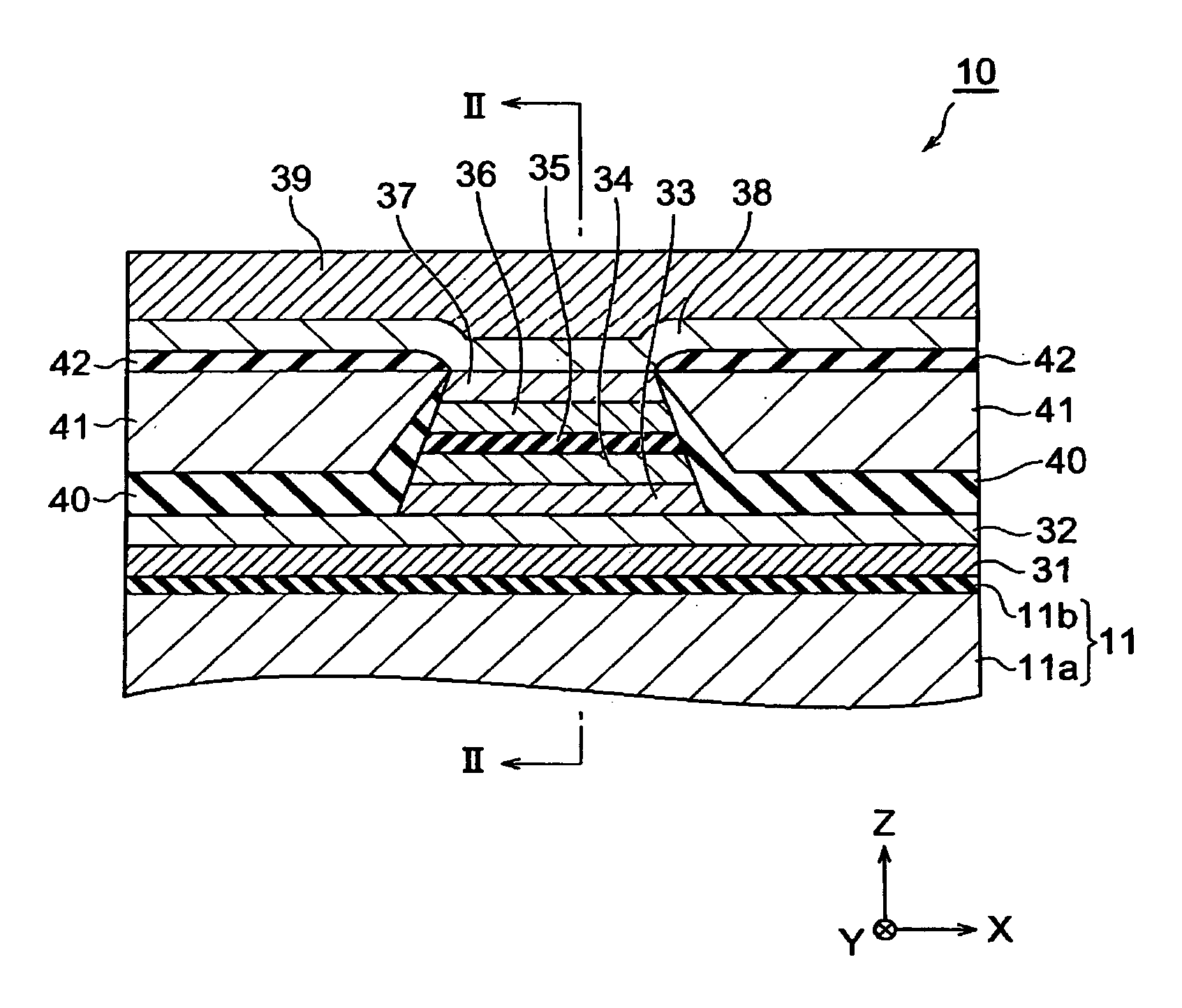
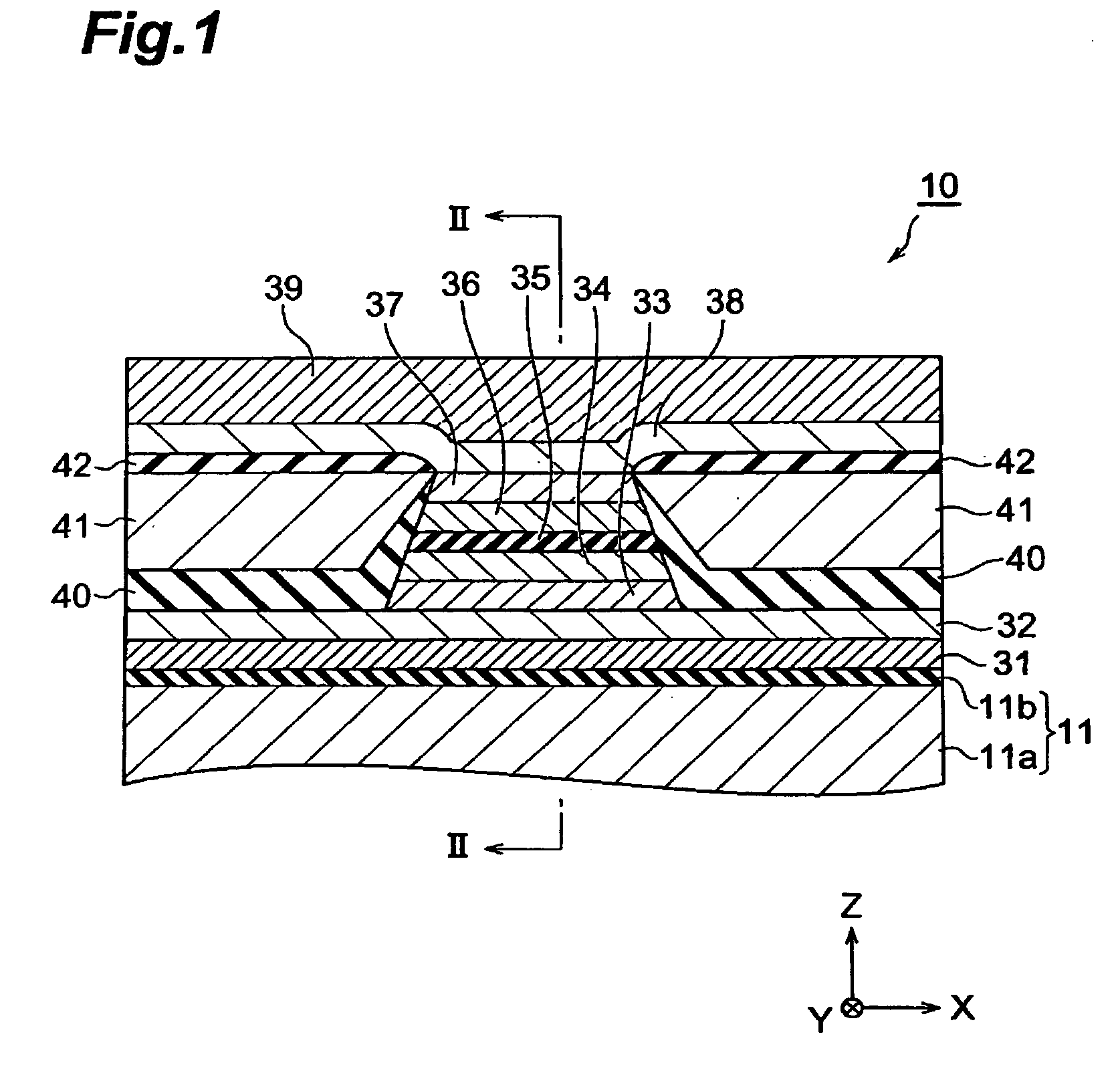
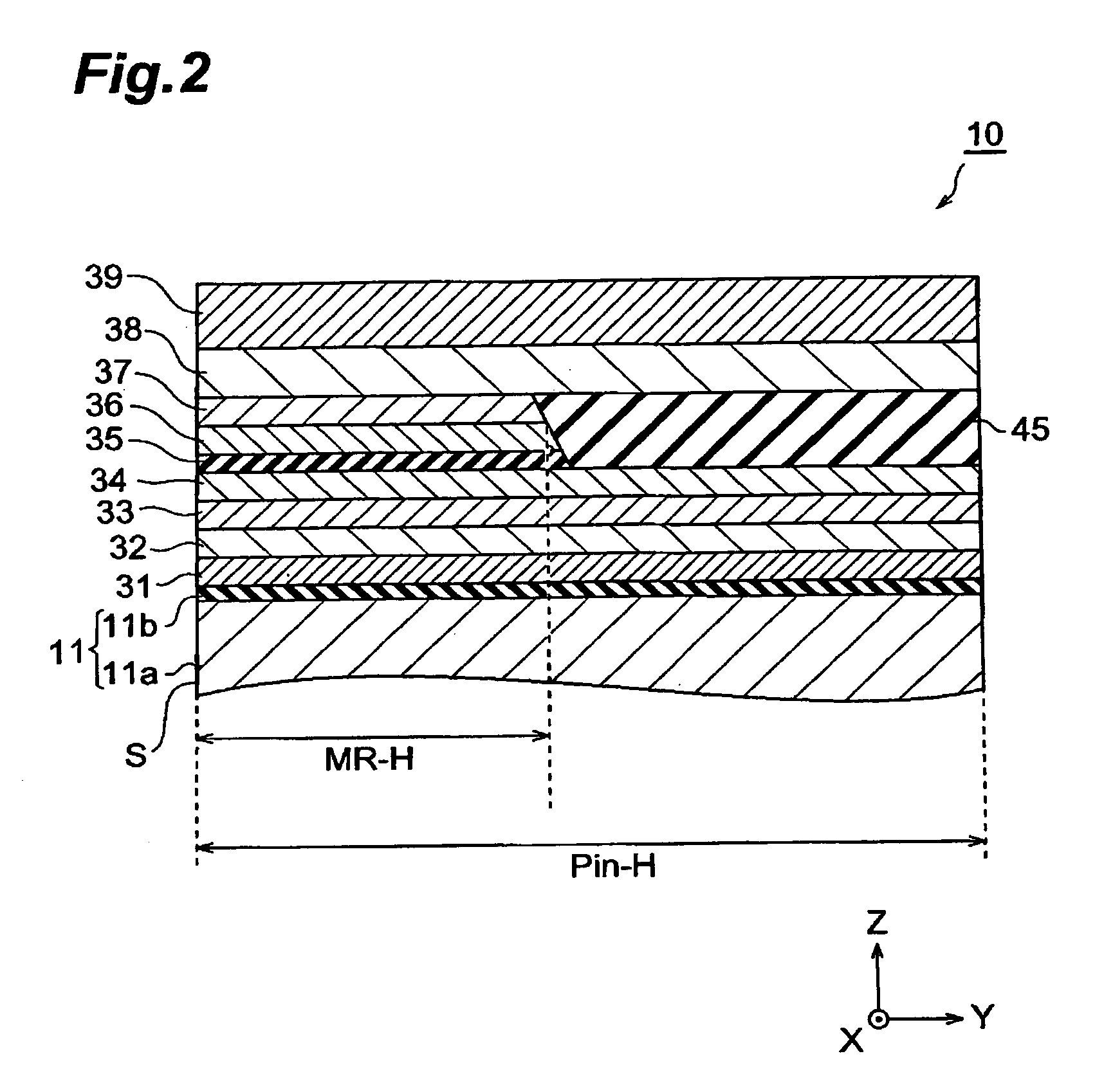
In the thin-film magnetic head of the present invention, the length of each of a pinned layer and an antiferromagnetic layer in their contact area in the depth direction from a surface facing a medium is longer than the length of a free layer in the same direction. When the length of the pinned layer in the depth direction is set longer as such, the direction of magnetization of the pinned layer can be restrained from being tilted by disturbances. Also, the pinned layer and the antiferromagnetic layer have the same length in their contact area in the MR height direction, so that the pinned layer is in contact with the antiferromagnetic layer throughout its length in the MR height direction, thus raising the exchange coupling force, whereby the inclination in the direction of magnetization can be suppressed more effectively.
Description
[0001] 1. Field of the Invention[0002] The present invention relates to a thin-film magnetic head, a head gimbal assembly, and a hard disk drive which read magnetic information of a hard disk or the like by utilizing a magnetoresistive effect.[0003] 2. Related Background Art[0004] As a thin-film magnetic head for reading magnetic information of a hard disk, MR (MagenetoResistive) heads have been in use. The MR heads utilize a magnetoresistive effect in which the ohmic value of a magnetic body varies as an external magnetic field (e.g., a leakage magnetic field from the hard disk) changes when a current is caused to flow through the magnetic body. This magnetoresistive effect can substantially be realized by an MR film comprising a pinned layer whose direction of magnetization is fixed by exchange coupling with an antiferromagnetic layer, a free layer whose direction of magnetization varies depending on the external magnetic field, an intermediate layer disposed therebetween, and the...
Claims
Login to View More Application Information
Patent Timeline
 IPC IPC(8): G11B5/00G11B5/012G11B5/31G11B5/39G11B5/48
CPCB82Y10/00B82Y25/00G11B5/012G11B5/3116G11B5/3163G11B2005/3996G11B5/3909G11B5/3932G11B5/4806G11B2005/0008G11B2005/0016G11B5/3903
InventorKAGAMI, TAKEOKASAHARA, NORIAKI
OwnerTDK CORPARATION