Method and apparatus for beverage dispensing nozzle

a beverage and nozzle technology, applied in the direction of liquid dispensing, liquid transferring device, packaging, etc., can solve the problems of excessive foaming, improper mixing, and residue of syrup, and achieve the effect of increasing the speed

Active Publication Date: 2005-03-03
LANCER PARTNERSHIP
View PDF4 Cites 39 Cited by
  • Summary
  • Abstract
  • Description
  • Claims
  • Application Information

AI Technical Summary

Benefits of technology

[0010] It is further an object of this invention to provide an increased

Problems solved by technology

Problems associated with multiple flavor dispensing nozzles include syrup carryover, proper mixing, and excessive foaming problems.
While the designs of the referenced patents address the foregoing problems, they did not address problems associated with delivery of products at lower flowrates for medium to low volume bever

Method used


Image

  • Method and apparatus for beverage dispensing nozzle
  • Method and apparatus for beverage dispensing nozzle
  • Method and apparatus for beverage dispensing nozzle

Examples


first embodiment

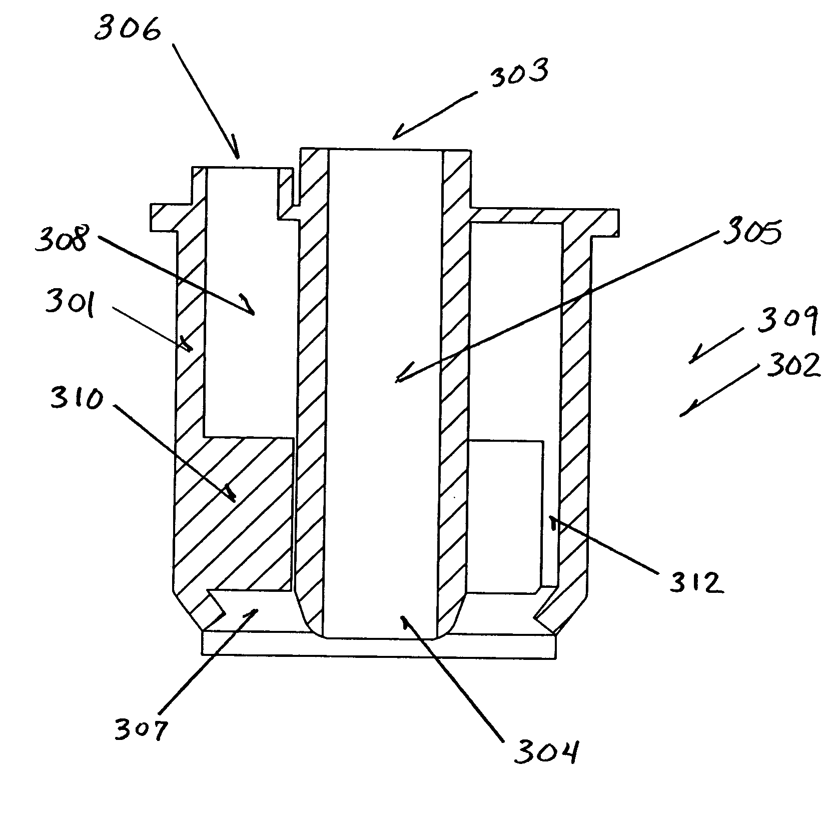
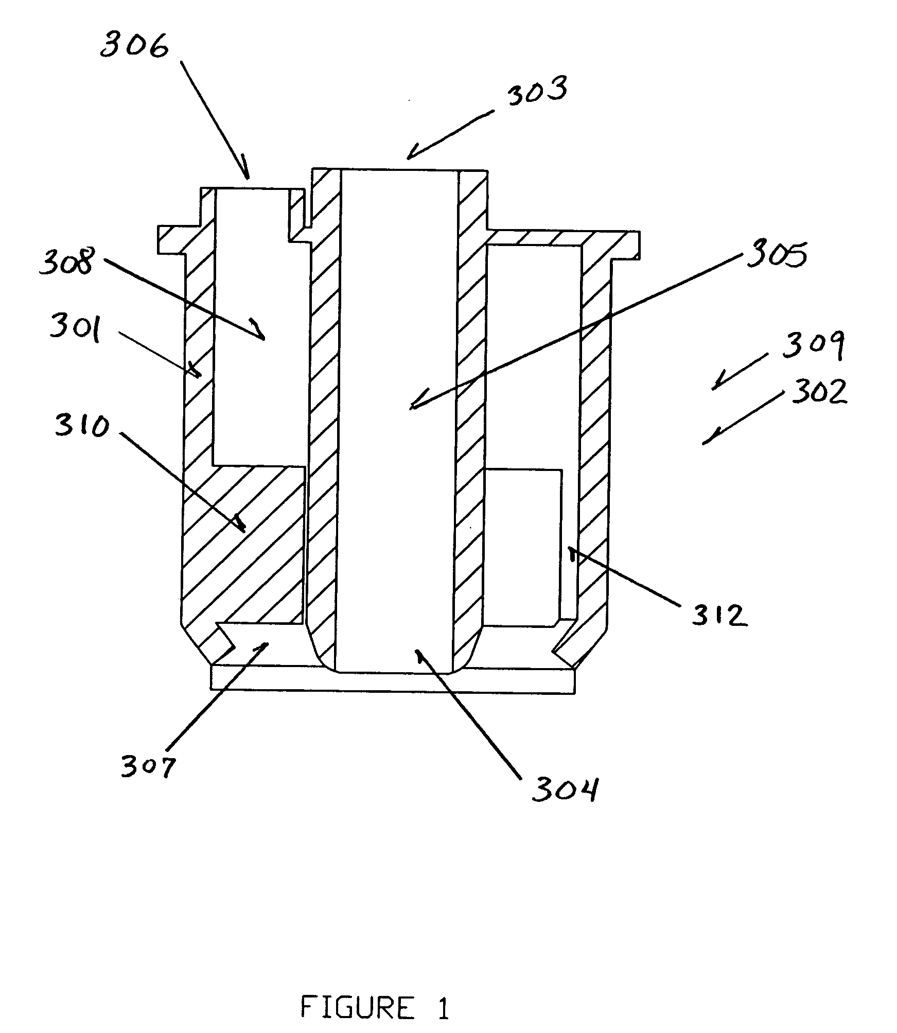
[0035] As shown in FIG. 1, a beverage dispensing nozzle 300 includes a body 301 having a single syrup flowpath 309 and a single mixing fluid flowpath 302. The syrup flowpath 309 includes a syrup inlet port 303, a syrup outlet port 304 and a beverage syrup channel 305. The mixing fluid flowpath 302 includes a mixing fluid inlet port 306, a mixing fluid outlet port 307 and a mixing fluid channel 308 disposed around the syrup flowpath 309. The mixing fluid channel 308 further includes at least one flow director 310 to increase the velocity of the mixing fluid. Multiple flow directors 310 may be used for increased control of the mixing fluid flow dynamics. The flow director 310 segments a lower portion of the large mixing fluid channel 308 into at least one smaller channel known as a flow director channel 312.

[0036] In operation, a beverage syrup is delivered to the beverage syrup inlet port 303 of the beverage dispensing nozzle 300 and a mixing fluid is delivered to the mixing fluid in...

second embodiment

[0038] In a second embodiment, a beverage dispensing nozzle 10 characteristic of the nozzle disclosed in the referenced U.S. Patents is equipped with an at least one flow director 200 to permit the nozzle 10 to operate at lower flowrates. As shown in FIGS. 3-7, the nozzle 10 includes a cap member 11, an o-ring 12, a plurality of gaskets 13-15, an inner housing 16, a first or outer annulus 17, a second or intermediate annulus 18, a third or inner annulus 19 and an outer housing 20. The inner housing 16 defines a chamber 40 and includes an opening 44 into the chamber 40. The inner housing 16 includes a plurality of cavities 41-43 that communicate with the chamber 40 through a plurality of conduits 45-47, respectively. The conduits 45-47 are concentrically spaced apart; namely, conduit 47 is innermost, conduit 45 is intermediate, and conduit 46 is outermost (see FIGS. 3-7). The conduits 45-47 are concentrically spaced apart so that beverage syrup may enter the chamber 40 at three separ...


PUM


Abstract

A method and apparatus for a beverage dispensing nozzle equipped with at least one flow director dispenses at lower flowrates. In a first embodiment, a single flavor beverage dispensing nozzle equipped with at least one flow director segments the flow and reduces the cross sectional area of the fluid stream, thereby forcing product to move downward. A second embodiment provides an improvement to an existing beverage dispensing nozzle, by adding at least one flow director in an annular channel of the beverage dispensing nozzle. The addition of the at least one flow director in the annular channel provides the beverage dispensing nozzle with the ability to dispense product at lower flowrates by increasing the velocity component of the exiting product. The exiting product now has sufficient energy to separate from the beverage dispensing nozzle. Methods for using the beverage dispensing nozzles with the at least one flow director are also presented.

Description

BACKGROUND OF THE INVENTION [0001] 1. Field of the Invention [0002] The present invention relates to beverage dispensing nozzles and more particularly, but not by way of limitation, to a beverage dispensing nozzle for use in dispensing medium to low flow applications. Further embodiments include dispensing flavor additives and dispensing multiple flavored drinks from a single nozzle without intermingling drink flavors. [0003] 2. Description of the Related Art [0004] In the food and beverage service industry, counter space is at a premium. As such, it is desirable to minimize the space requirements of counter top dispensers through dispensing multiple flavors of drinks, including flavor additives, from a single nozzle. Problems associated with multiple flavor dispensing nozzles include syrup carryover, proper mixing, and excessive foaming problems. U.S. Pat. Nos. 6,098,842, 6,047,859 and 6,345,729 disclose multiple flavor nozzles that provide solutions to these problems. These multip...

Claims


Application Information

Patent Timeline
IPC IPC(8): B67D1/00B67D7/74
CPCB67D1/0043B67D1/0052B67D1/0051B67D1/0044B67D1/12B67D7/74B67D1/08
Inventor SANTY, JOHN D. JR.
Owner LANCER PARTNERSHIP
Why Eureka
Try Eureka