Mounting apparatus for data storage device

mounting device technology, applied in the direction of electrical apparatus casings/cabinets/drawers, coupling device connections, instruments, etc., can solve the problems of inconvenient mounting, inconvenient mounting, and inability to attach a data storage device to a drive bracket with bolts, etc., to achieve convenient attachment and removal of the data storage device. , the effect of simple structur

Inactive Publication Date: 2005-03-17
HON HAI PRECISION IND CO LTD
View PDF5 Cites 37 Cited by
  • Summary
  • Abstract
  • Description
  • Claims
  • Application Information

AI Technical Summary

Benefits of technology

[0007] Accordingly, an object of the present invention is to provide a mounting apparatus with a simple structure which readily allows attachment and removal of a data storage device to and from a chassis.
[0008] Another object of the present invention is to provide a mounting apparatus which is configured to be good at grounding and anti-vibration.
[0009] To achieve the above-mentioned object, a mounting apparatus in accordance with the preferred embodiment of the present invention is used to mount a data storage device in a computer chassis. The mounting apparatus comprises a drive bracket, a support bracket received in the drive bracket and a latch attached to a side wall of the drive bracket. A plurality of slots is defined in both side walls of the drive bracket. Each slot communicates with an upper edge of the side wall via an entry. The support bracket comprises a base and a pair of side plates. A plurality of positioning tabs formed inwardly from the support bracket to engage with the data storage device. A plurality of resilient members extends slightly outwardly from the support bracket to abut against the drive bracket for better grounding and anti-vibration. A plurality of pins extends outwardly from the side plates for slideably engaging in the slots of the drive bracket. The latch has a main body and a resilient fastening portion. The fastening portion removably engages with the corresponding pin therefore securing the data storage device in the drive bracket. When pressing a handle of the latch, the fastening portion will be driven to release the pin.
[0010] In this invention, the support bracket is received in the drive bracket with the pins slid in the slots, and by means of the latch attached to the drive bracket to secure one of the pins, so that the combined data storage device and support bracket is attached to the drive bracket. That is to say, the data storage device is secured to the drive bracket without screws, therefore simplifies the attachment and removal procedures.

Problems solved by technology

Fixing a data storage device to a drive bracket with bolts is unduly laborious and time-consuming.
Furthermore, the computer enclosure needs extra operating space for carrying out the fixing operation.
However, certain bolts are still needed to fix the rails to the drive bracket.
This may cause electromagnetic interference (EMI) problems, and may lead to accumulation of static charges on the computer enclosure.
This not only restricts grounding connection options between the data storage device and the drive bracket, but also tends to lead to extra maintenance because of the plastic rails easily wearing out and needing replacement.

Method used


Image

  • Mounting apparatus for data storage device
  • Mounting apparatus for data storage device
  • Mounting apparatus for data storage device

Examples


Embodiment Construction

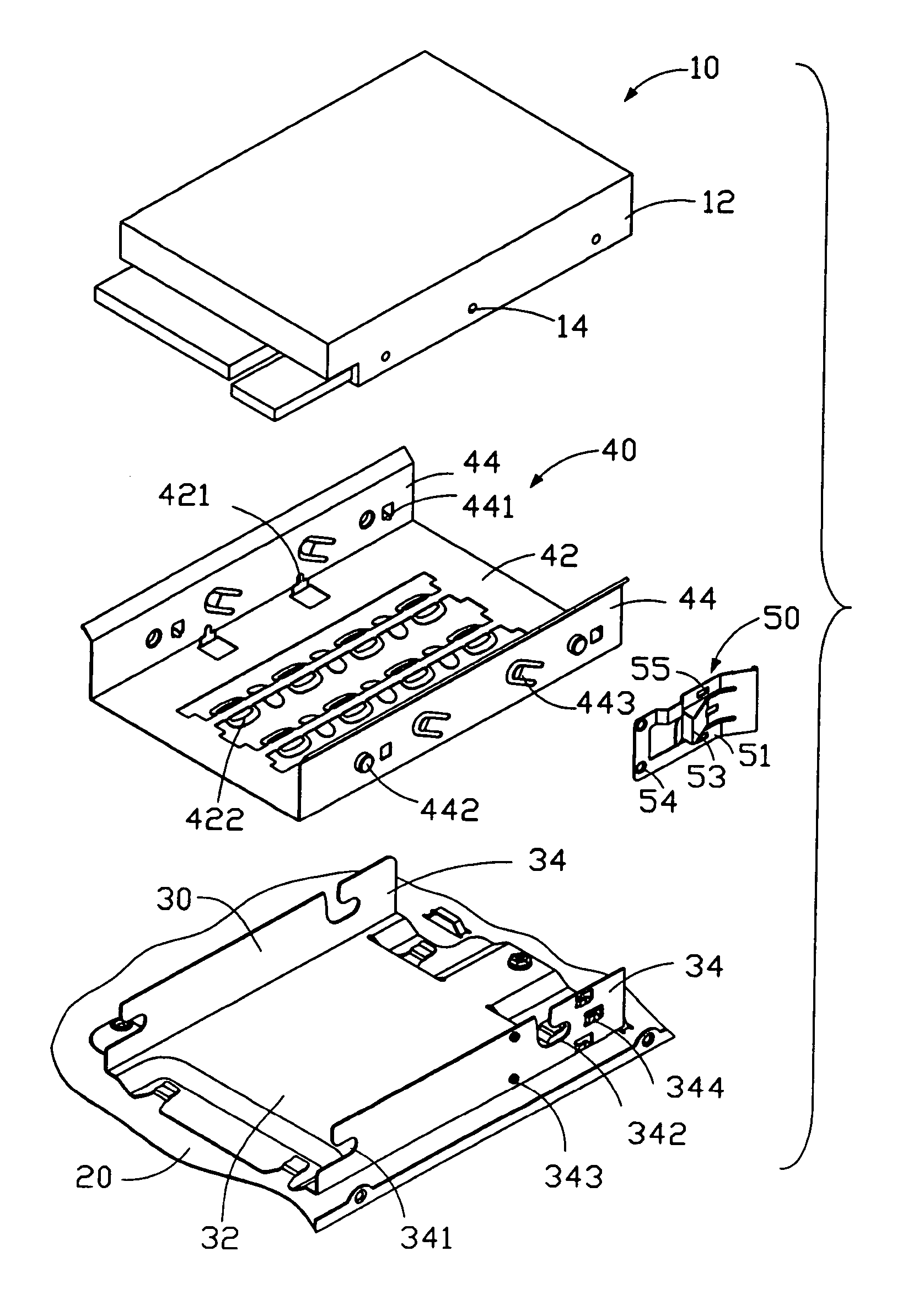
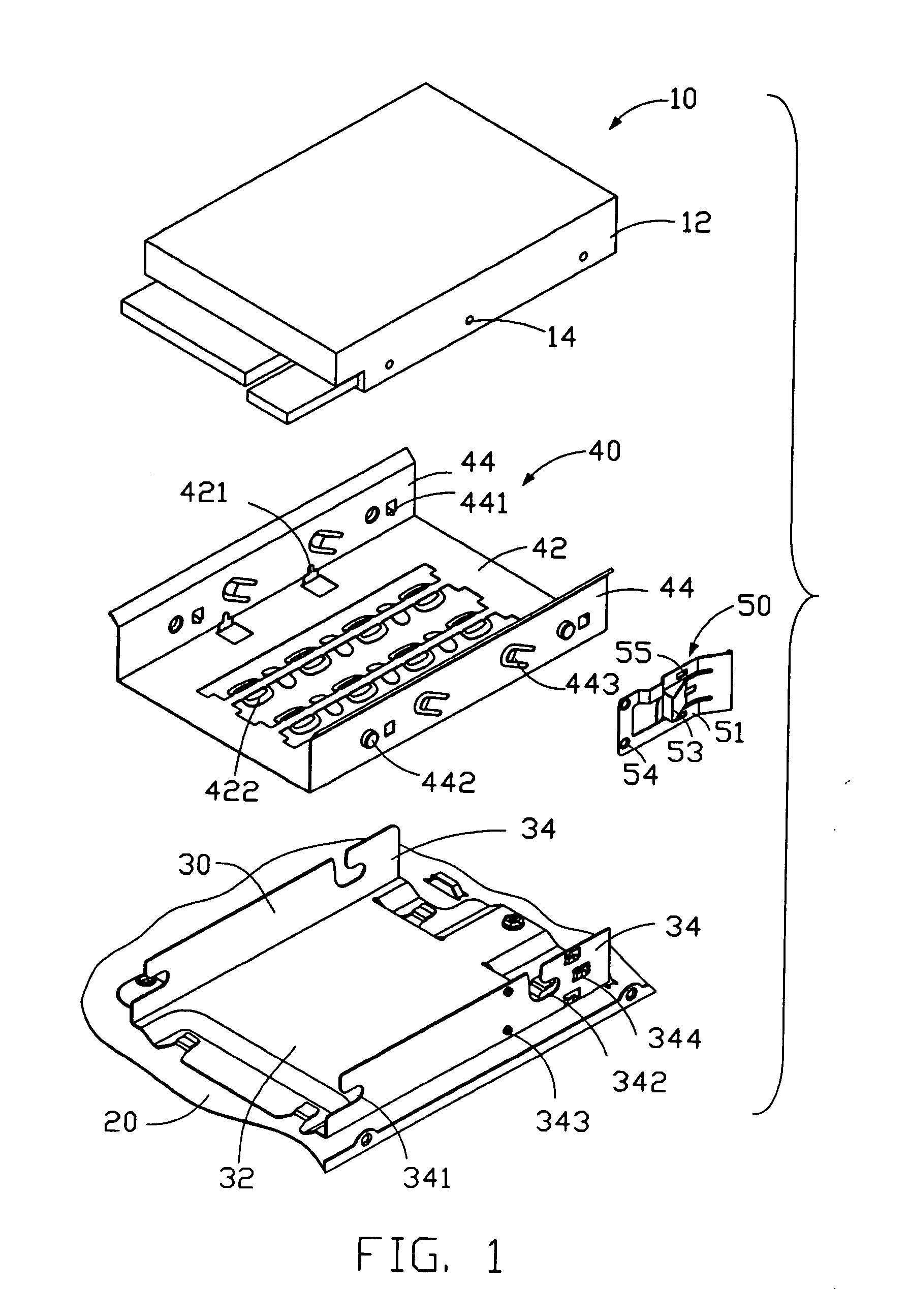
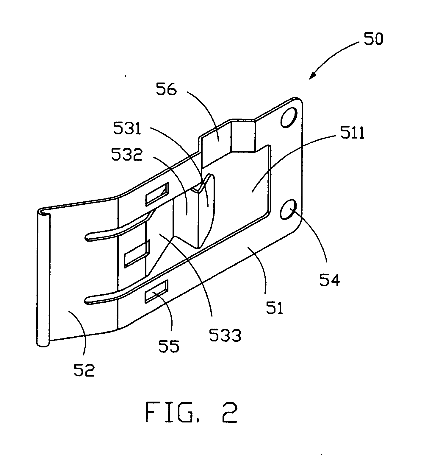
[0016] Referring to FIG. 1, a mounting apparatus in accordance with the preferred embodiment of the present invention is used for securing a data storage device 10 to a bottom panel 20 of a computer chassis (not shown). The mounting apparatus comprises a drive bracket 30, a support bracket 40, and a latch 50.

[0017] The data storage device 10 comprises a pair of side facets 12 each defining a plurality of apertures 14.

[0018] The drive bracket 30 is attached to the bottom panel 20 of the computer chassis by conventional means. The drive bracket 30 comprises a bottom wall 32 and a pair of side walls 34 extending upwardly from opposite sides of the bottom wall 32. The side walls 34 each define a first guiding slot 341 and a second guiding slot 342. The guiding slots 341, 342 communicate with top edges of the side walls 34 via entries. In the preferred embodiment, each first guiding slot 341 also communicates with an end of the corresponding side wall 34. A plurality of L-shaped catche...


PUM


Abstract

A mounting apparatus for mounting a data storage device (10) to a chassis (20), includes a drive bracket (30), a support bracket (40) received in the drive bracket and a latch (50) attached to a side wall (34) of the drive bracket. A plurality of slots (341, 342) is defined in both side walls of the drive bracket. Each slot communicates with an upper edge of the side wall via an entry. The support bracket includes a base (42) and a pair of side plates (44) for receiving the data storage device therebetween. A plurality of pins (442) extends outwardly from the side plates for slideably engaging in the slots of the drive bracket. The latch has a main body (51) and a resilient fastening portion (53). The fastening portion removably engages with the corresponding pin therefore securing the data storage device in the drive bracket.

Description

BACKGROUND OF THE INVENTION [0001] 1. Field of the Invention [0002] The present invention relates to mounting apparatuses for data storage devices, and particularly to a mounting apparatuses for readily attaching a data storage device to a computer enclosure. [0003] 2. Description of the Related Art [0004] Generally speaking, when a computer is assembled, a drive bracket is mounted in a computer enclosure, and then data storage devices are fixed to the drive bracket. The data storage devices comprise various combinations of hard disk drives (HDDs), floppy disk drives (FDDs), and compact disk-read only memory (CD-ROM) drives. [0005] A conventional data storage device is generally attached to a drive bracket by bolts or rails. Examples are disclosed in Taiwan Patent Application No. 81207129 and U.S. Pat. No. 6,304,457. Fixing a data storage device to a drive bracket with bolts is unduly laborious and time-consuming. Furthermore, the computer enclosure needs extra operating space for c...

Claims


Application Information

Patent Timeline
Patent Type & Authority Applications(United States)
IPC IPC(8): G06F1/18
CPCG06F1/187G06F1/184
Inventor CHEN, YUN LUNGSHI, CHUAN MIN
Owner HON HAI PRECISION IND CO LTD
Why Eureka
Try Eureka