Angular-rate detecting apparatus

a detection apparatus and angular rate technology, applied in the direction of acceleration measurement using interia force, turn-sensitive devices, instruments, etc., can solve the problems of deterioration in the performance at the time of startup or an increase in power consumption, deterioration in the detection accuracy or reliability required as a sensor, etc., to achieve the effect of improving detection accuracy and reliability

Active Publication Date: 2005-03-31
MURATA MFG CO LTD
View PDF8 Cites 19 Cited by
  • Summary
  • Abstract
  • Description
  • Claims
  • Application Information

AI Technical Summary

Benefits of technology

[0011] To overcome the above-described problems, preferred embodiments of the present invention provide an angular-rate detecting apparatus in which two mass portions adjacent to each other a...

Problems solved by technology

Accordingly, in the known art, a vibration mode other than the normal vibration mode is likely to be excited, for example, at the time of starting up the sensor, as a result, a period of startup time from startup of the sensor to excitation of the normal vibration mode is longer or a drive signal at a high signal level (a high voltage) is needed to be inputted into the vibration generator in order to excite and maintain the normal...

Method used


Image

  • Angular-rate detecting apparatus
  • Angular-rate detecting apparatus
  • Angular-rate detecting apparatus

Examples


Embodiment Construction

having a vibration mode that is different from the normal vibration mode;

[0034]FIG. 4 illustrates Comparative Example 2 having a vibration mode that is different from the normal vibration mode;

[0035]FIG. 5 illustrates Comparative Example 3 having a vibration mode that is different from the normal vibration mode;

[0036]FIG. 6 illustrates Comparative Example 4 in which each mass portion is displaced due to a static drive force when only outer mass portions are driven;

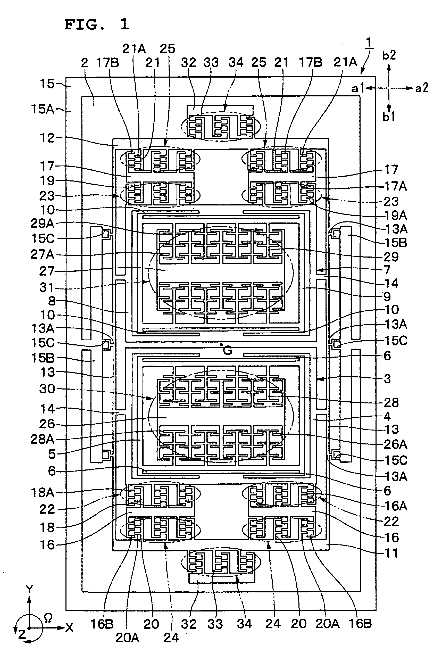
[0037]FIG. 7 is a plan view of an angular rate sensor according to a second preferred embodiment of the present invention;

[0038]FIG. 8 illustrates the structure of a control circuit of the angular rate sensor; and

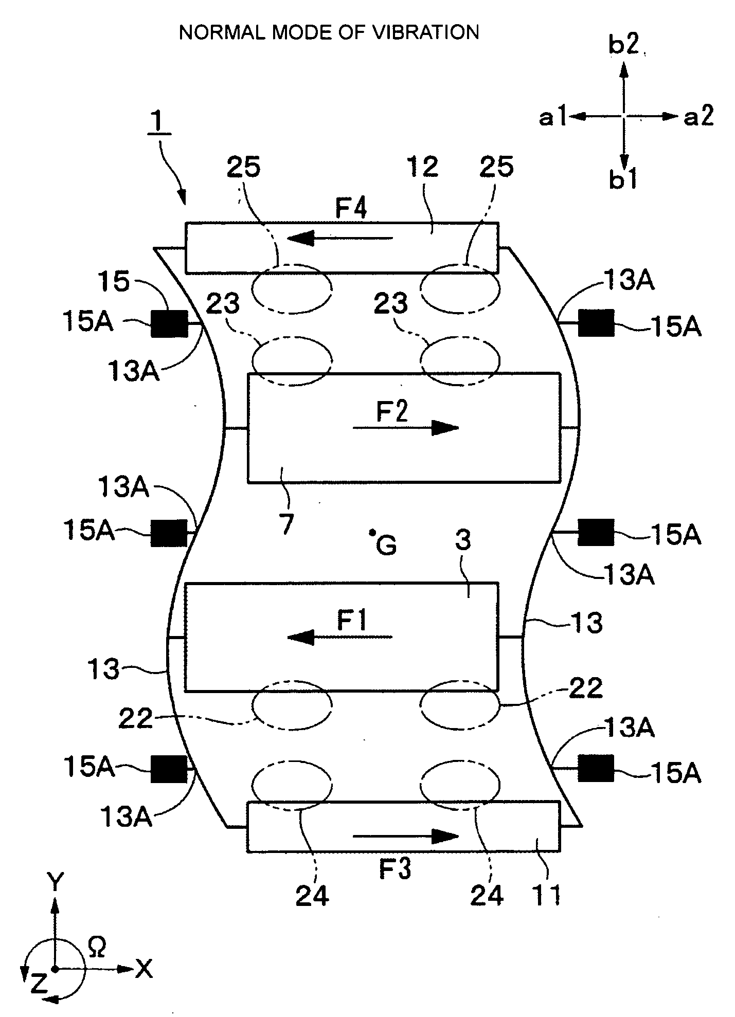
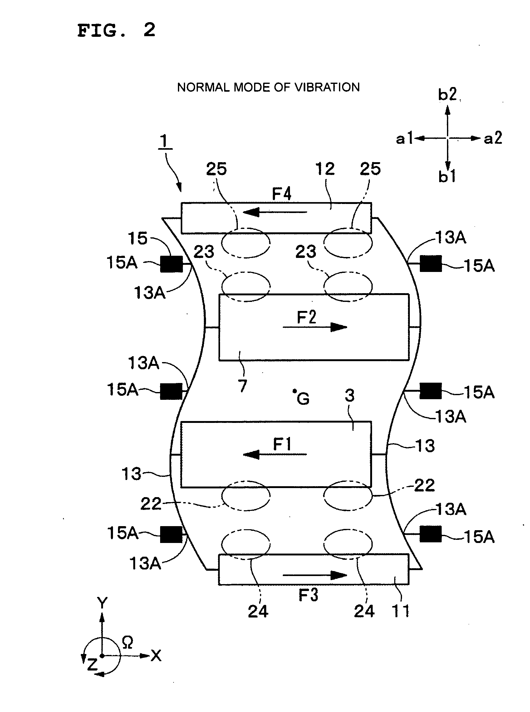
[0039]FIG. 9 is a characteristic diagram illustrating the relationship between drive signal and normal monitor signal when the mass portions vibrate in the normal vibration mode.

DETAILED DESCRIPTION OF PREFERRED EMBODIMENTS

[0040] An angular-rate detecting apparatus according to preferred embodiments of the ...


PUM


Abstract

An Angular-rate detecting apparatus includes four mass portions connected by at least one support beam, and the mass portions have respective individual vibration generators disposed thereon. The individual vibration generators excite the normal vibration mode by vibrating pairs of the mass portions adjacent to each other in opposite phases. Thus, the mass portions are forcibly vibrated in the normal vibration mode. Angular rate detectors detect displacements of inner frames of central mass portions as an angular rate about an axis perpendicular to a detection direction and also to a vibration direction when the inner frames are displaced in the detection direction while vibrating in the vibration direction.

Description

BACKGROUND OF THE INVENTION [0001] 1. Field of the Invention [0002] The present invention relates to an angular-rate detecting apparatus for detecting an angular rate of a rotating body. [0003] 2. Description of the Related Art [0004] A known angular-rate detecting apparatus is an angular rate sensor which detects a displacement of a mass portion due to a Coriolis force as an angular rate by utilizing the principle that a mass portion vibrating in a given direction undergoes a Coriolis force in accordance with an angular rate (for example, see Japanese Unexamined Patent Application Publication No. 2002-81939). [0005] Such an angular rate sensor according to the known art includes three mass portions that are juxtaposed to one another on a substrate, and these mass portions are connected by support beams so as to be vibratable in the X-axis direction. Also, each support beam has fixing portions, each disposed between two of the mass portions so as to fix central longitudinal portions...

Claims


Application Information

Patent Timeline
IPC IPC(8): G01C19/56G01P3/483G01C19/5719G01C19/5747
CPCG01C19/5719G01P3/483
Inventor MOCHIDA, YOICHI
Owner MURATA MFG CO LTD
Why Eureka
Try Eureka