Tube fixing structure and fixing member used therefor

a technology for fixing structures and tubes, applied in the direction of hose connections, couplings, mechanical devices, etc., can solve the problems of plastic deformation, creeping or scratching, and the air tightness and stability of tubes with creeping or scratching would be significantly deteriorated, so as to prevent vaporization of moisture and improve air tightness and stability.

Inactive Publication Date: 2005-05-26
BROTHER KOGYO KK
View PDF18 Cites 3 Cited by
  • Summary
  • Abstract
  • Description
  • Claims
  • Application Information

AI Technical Summary

Benefits of technology

[0005] Although the aforementioned technique adopts a flexible tube, a rigid tube having vapor permeability and gas permeability may sometimes be adopted in order to prevent vaporization of moisture of ink contained in the tube and also to prevent entry of air from outside into the tube. In this case, the tube may incur plastic deformation and cause creeps or scratches at the time of being attached to the connector, because an outer surface of the connector of the joint is uneven. A tube having creeps or scratches would be significantly deteriorated in airtightness and stability. Even if creeps or scratches are not caused, the tube incurs plastic deformation and therefore repetitive attachment / detachment of the tube to / from the joint is disadvantageously affects airtightness and stability of the tube.
[0006] An object of the present invention is to provide a tube fixing structure capable of maintaining good airtightness and stability even when a rigid tube is adopted, and also to provide a fixing member used for the tube fixing structure.
[0008] According to the aforementioned aspect, the outer surface of the pipe of the joint is flattened with respect to its axial direction. Therefore, even when a rigid tube is adopted, the tube exhibits no excessive deformation and thus airtightness and stability of the tube can be kept well. In addition, since deformation of the tube is suppressed, repetitive attachment / detachment of the tube to / from the joint does not deteriorate the airtightness and stability of the tube. Therefore, excellent maintenability can be obtained. Further, when the tube is held by the holder of the fixing member, the slit is expanded in accordance with the rigidity of the tube and then the tube disposed within the through hole receives appropriate cramping force. This can surely fix the tube to the joint.

Problems solved by technology

In this case, the tube may incur plastic deformation and cause creeps or scratches at the time of being attached to the connector, because an outer surface of the connector of the joint is uneven.
A tube having creeps or scratches would be significantly deteriorated in airtightness and stability.
Even if creeps or scratches are not caused, the tube incurs plastic deformation and therefore repetitive attachment / detachment of the tube to / from the joint is disadvantageously affects airtightness and stability of the tube.

Method used


Image

  • Tube fixing structure and fixing member used therefor
  • Tube fixing structure and fixing member used therefor
  • Tube fixing structure and fixing member used therefor

Examples


Embodiment Construction

[0027] In the following, a certain preferred embodiment of the present invention will be described in conjunction with the accompanying drawings.

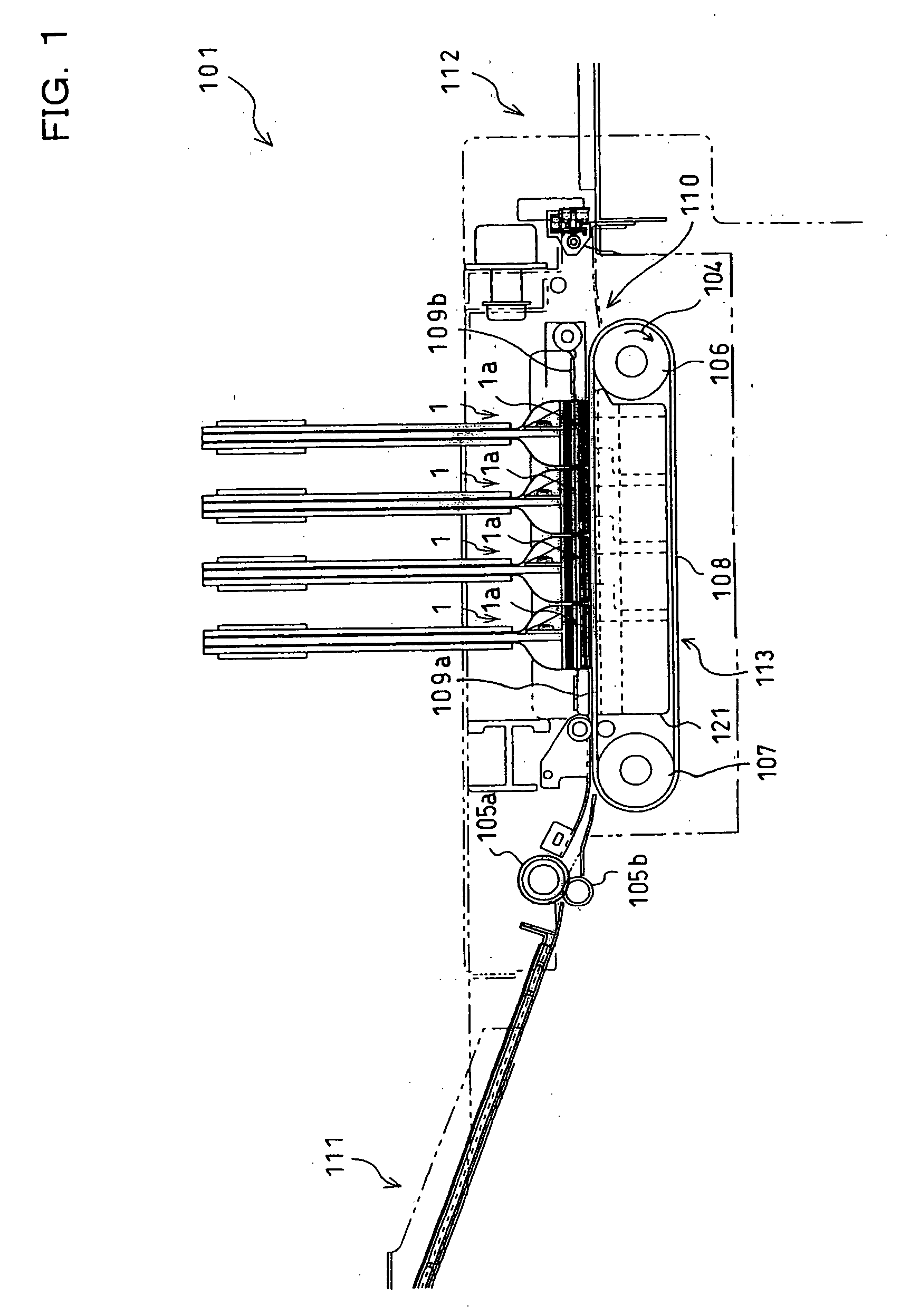
[0028] First, referring to FIG. 1, a description will be given to a general construction of an ink-jet printer that adopts a tube fixing structure according to a first embodiment of the present invention. An ink-jet printer 101 of this embodiment is a color printer having four ink-jet heads 1. The printer 101 includes a paper feed unit 111 (as shown lefthand in FIG. 1) and a paper discharge unit 112 (as shown righthand in FIG. 1). Within the printer 101, formed is a paper conveyance path running from the paper feed unit 111 to the paper discharge unit 112.

[0029] A pair of paper feed rollers 105a and 105b are disposed immediately downstream from the paper feed unit 111, so that the rollers 105a and 105b can pinch a paper as a record medium which is in this condition conveyed from left to right in FIG. 1. In a middle of the paper conveyance...


PUM

PropertyMeasurementUnit
diameteraaaaaaaaaa
diameteraaaaaaaaaa
diameteraaaaaaaaaa

Abstract

In a tube fixing structure, a tube is fixed to a joint by means of a fixing member. The joint comprises a pipe whose one end is fitted into the tube, whose outside diameter is larger than an inside diameter of the tube, and whose outer surface is flattened with respect to the axial direction; and a main body that is connected with the other end of the pipe. The fixing member comprises a cylindrical holder made of a flexible material, which holds a portion of the tube having the pipe fitted therein by cramping the portion from its outer periphery, the holder having a through hole into which the tube is coaxially disposed and a slit formed to reach the through hole.

Description

BACKGROUND OF THE INVENTION [0001] 1. Field of the Invention [0002] The present invention relates to a structure for fixing a tube to a joint, and also to a fixing member used in this structure. [0003] 2. Description of Related Art [0004] In an ink-jet head that performs a recording by ejecting ink onto a record medium, according to a known technique, an ink supply source such as ink tank supplies ink via a tube (see U.S. Patent Publication No. 2003 / 0048336A1). The head according to this technique includes therein an air trap unit and a joint. The air trap unit accommodates air bubbles generated in the tube. The joint is disposed between the air trap unit and the tube, and connects them. A connector for connecting the joint with the tube is provided at one end of the joint opposite to the air trap, to protrude therefrom. The connector is made up of a tapered head and a neck. A maximum diameter of the head is larger than an inside diameter of the tube, and the head has its diameter d...

Claims


Application Information

Patent Timeline
Patent Type & Authority Applications(United States)
IPC IPC(8): B41J2/175F16B2/22F16L33/03F16L33/10F16L37/04
CPCF16L33/03B41J2/175
Inventor TAKAGI, OSAMU
Owner BROTHER KOGYO KK
Why Eureka
Try Eureka