Retention device

a technology of retention device and hook, which is applied in the direction of fastening means, dowels, mechanical apparatus, etc., can solve the problems of shortening the service life of the hook retention device and unappealing outer appearance, and achieves simple and easy assembly, attractive appearance, and support a heavy load

Inactive Publication Date: 2005-06-16
WANG SAN S
View PDF14 Cites 23 Cited by
  • Summary
  • Abstract
  • Description
  • Claims
  • Application Information

AI Technical Summary

Benefits of technology

[0014] Therefore, the object of the present invention is to provide a retention device that is simple and easy to assemble, that can support a heavy load, and that has an appealing appearance.

Problems solved by technology

Since friction between the side walls 113, 123 and the ceiling 2 is small, the anchor plates 11, 12 are likely to rotate idly along with the hook 16, thereby resulting in inconveniences during assembly of the conventional hook retention device 1.
When the hook 16 bears a heavy load, it is easily damaged because only the nut 14, which is a thin plate, serves as a load bearing point for the whole load, thereby resulting in a shorten service life for the hook retention device 1.
However, the resulting outer appearance is unappealing.

Method used


Image

  • Retention device
  • Retention device
  • Retention device

Examples


Embodiment Construction

[0028] Before the present invention is described in greater detail, it should be noted that like elements are denoted by the same reference numerals throughout the disclosure.

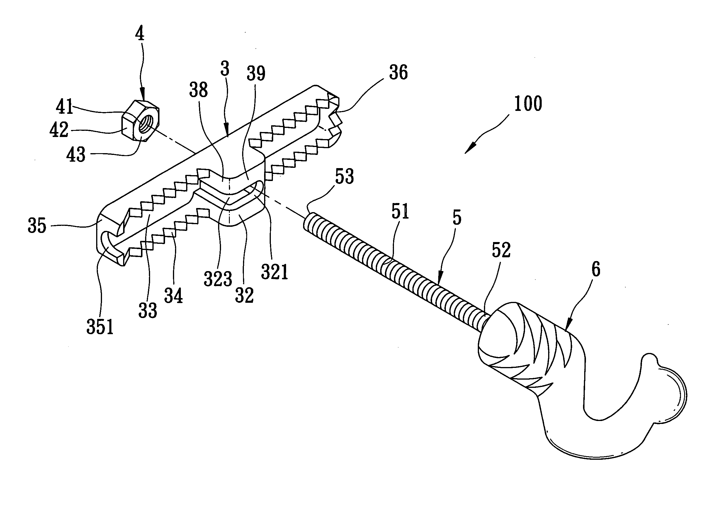
[0029] Referring to FIGS. 5 and 6, the first preferred embodiment of a retention device 100 according to the present invention is shown to comprise a one-piece longitudinal anchor member 3, a nut 4, and a screw rod 5. The retention device 100 further has a hook 6 provided at one end of the screw rod 5.

[0030] The anchor member 3 has longitudinally opposed first and second ends 35, 36, a nut retaining part 32 formed between the first and second ends 35, 36, an anchoring surface 34 extending from the first end 35 to the second end 36, and a receiving space 33 formed in the anchoring surface 34. The first end 35 is formed with a notch 351 that is in spatial communication with the receiving space 33. The nut retaining part 32 protrudes outwardly from the anchoring surface 34 in a direction transverse to the anchor...


PUM


Abstract

A retention device includes a one-piece longitudinal anchor member having opposed first and second ends, a nut retaining part formed between the first and second ends, a through hole extending through the nut retaining part, and an engagement surface around the through hole. A screw rod extends through the through hole and engages threadedly a nut, and is turnable between folded and unfolded positions, in which the screw rod is moved toward and away from the first end, respectively. The nut is movable within the through hole between engaging and non-engaging positions. The nut engages and disengages the engagement surface in the engaging and non-engagement positions when the screw rod is in the unfolded and folded positions, respectively.

Description

BACKGROUND OF THE INVENTION [0001] 1. Field of the Invention [0002] The invention relates to a retention device, more particularly to a retention device for a hook. [0003] 2. Description of the Related Art [0004] Referring to FIGS. 1 and 2, a conventional hook retention device 1 is applicable on a wall surface or a ceiling 2 (see FIGS. 3 and 4), and includes two anchor plates 11, 12, a torsion spring 13, a nut 14, and a screw rod 15. [0005] Each of the anchor plates 11, 12 is generally U-shaped, and has a main wall 111, 121, two opposite side walls 113, 123 that extend downwardly and respectively from two side edges of the main wall 111, 121 and that cooperate with the main wall 111, 121 to define a receiving space 112, 122, a pair of aligning holes 114, 224 formed in inner ends of the side walls 113, 123, and a groove 115, 125 formed in an inner end of the main wall 111, 121. The grooves 115, 125 in the main walls 111, 121 of the anchor plates 11, 12 cooperate to form a circular ho...

Claims


Application Information

Patent Timeline
Patent Type & Authority Applications(United States)
IPC IPC(8): F16B13/08F16B21/00
CPCF16B13/0833F16B13/0808
Inventor WANG, SAN S.
Owner WANG SAN S
Why Eureka
Try Eureka