
Ink refill unit with keyed connection ink cartridge
a technology of ink cartridges and refill units, applied in the field of printers, can solve the problems of reducing the scope of users who inadvertently mismatch the refill color and the interface color, and achieve the effect of avoiding inadvertent ink leakag
- Summary
- Abstract
- Description
- Claims
- Application Information
AI Technical Summary
Benefits of technology
Problems solved by technology
Method used
Image

Examples
Embodiment Construction
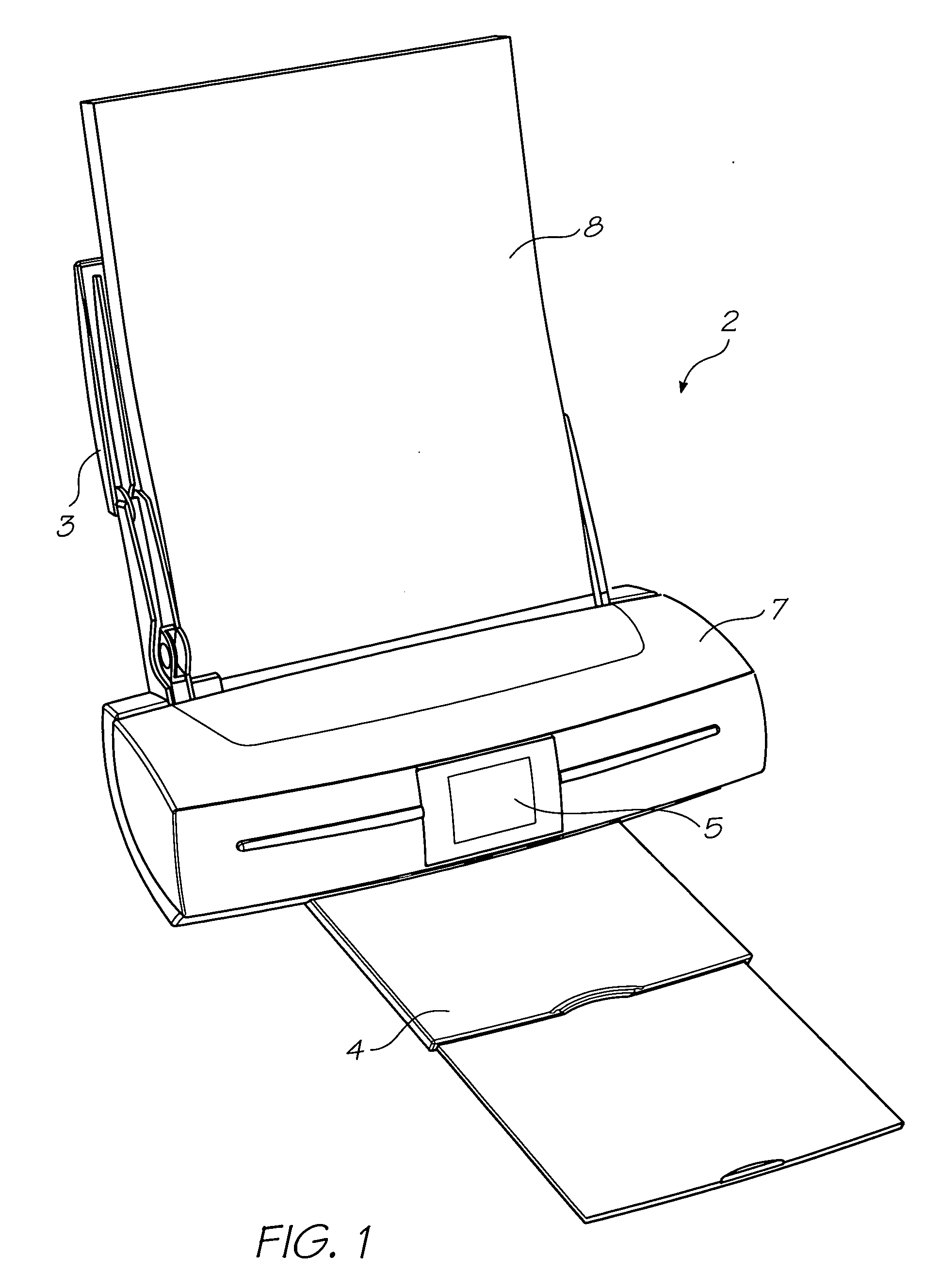
[0257]FIG. 1 shows a printer unit 2 embodying the present invention. Media supply tray 3 supports and supplies media 8 to be printed by the print engine (concealed within the printer casing). Printed sheets of media 8 are fed from the print engine to a media output tray 4 for collection. User interface 5 is an LCD touch screen and enables a user to control the operation of the printer unit 2.
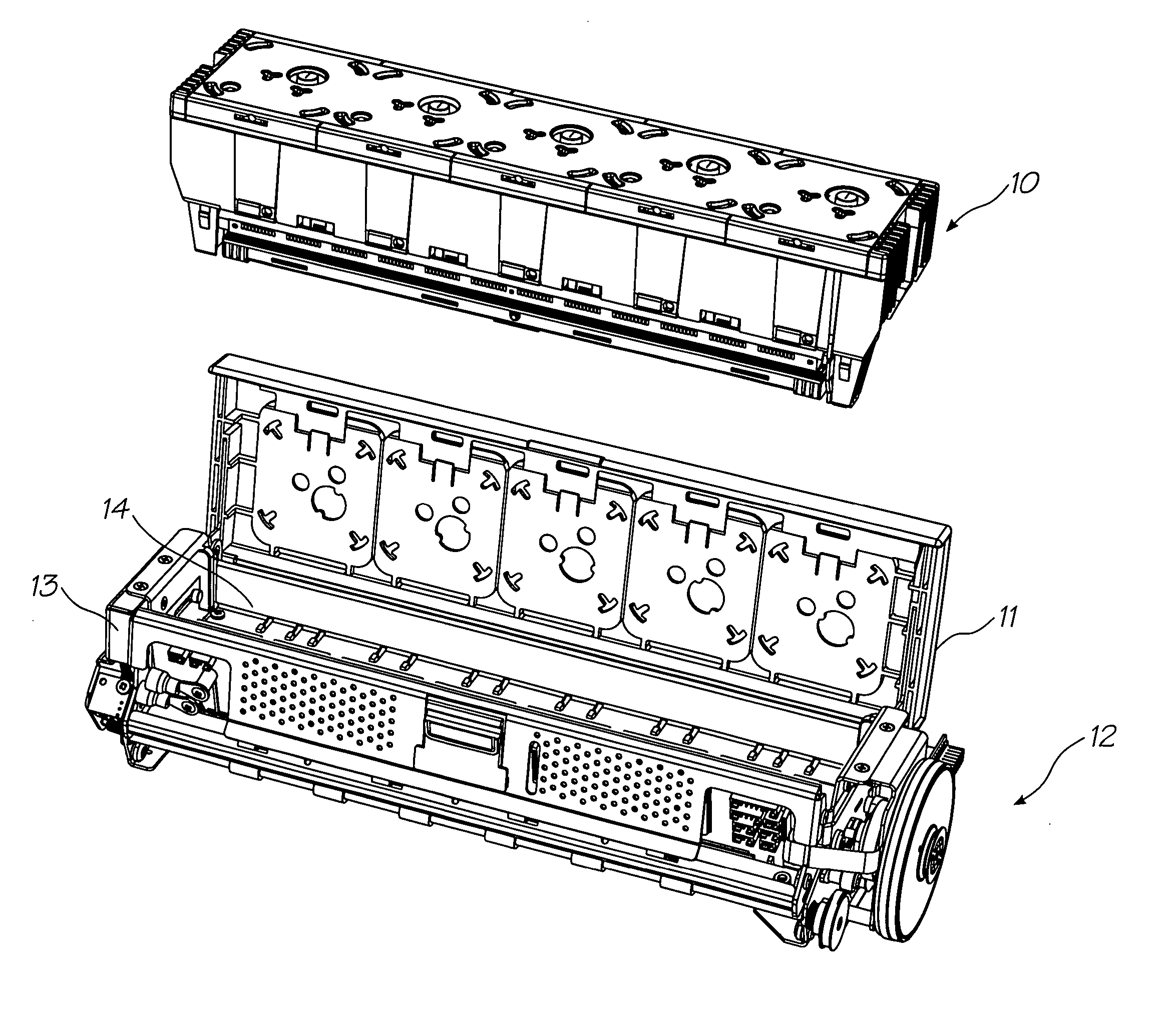
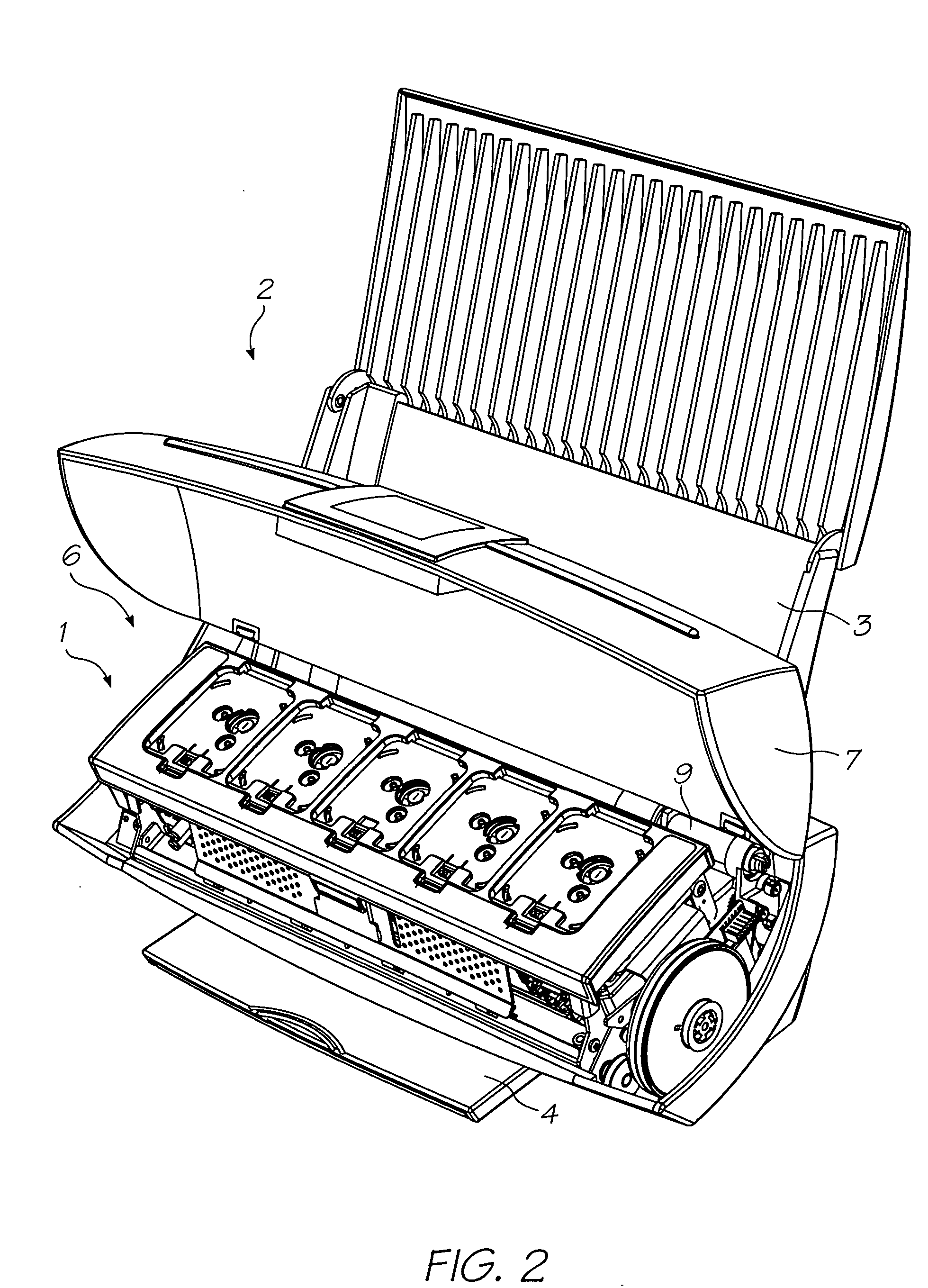
[0258]FIG. 2 shows the lid 7 of the printer unit 2 open to expose the print engine 1 positioned in the internal cavity 6. Picker mechanism 9 engages the media in the input tray 3 (not shown for clarity) and feeds individual streets to the print engine 1. The print engine 1 includes media transport means that takes the individual sheets and feeds them past a printhead assembly (described below) for printing and subsequent delivery to the media output tray 4 (shown retracted).
[0259]FIG. 3 schematically shows how the printer unit 2 is arranged to print documents received from an external source, ...
PUM
 Abstract
Description
Claims
Application Information