

Method for minimizing bowing of collector plates in an electrostatic precipitator, and a collector plate-clip combination
a technology of electrostatic precipitator and collector plate, which is applied in the direction of electrostatic separation, electrostatic cleaning, chemistry apparatus and processes, etc., can solve the problems of reducing clearance, affecting the performance of charging particles, and the over-all performance of precipitator, so as to minimize the bowing of a fresh plate, prevent the bowing, and facilitate the straightening of a collecting plate
- Summary
- Abstract
- Description
- Claims
- Application Information
AI Technical Summary
Benefits of technology
Problems solved by technology
Method used
Image

Examples
first embodiment
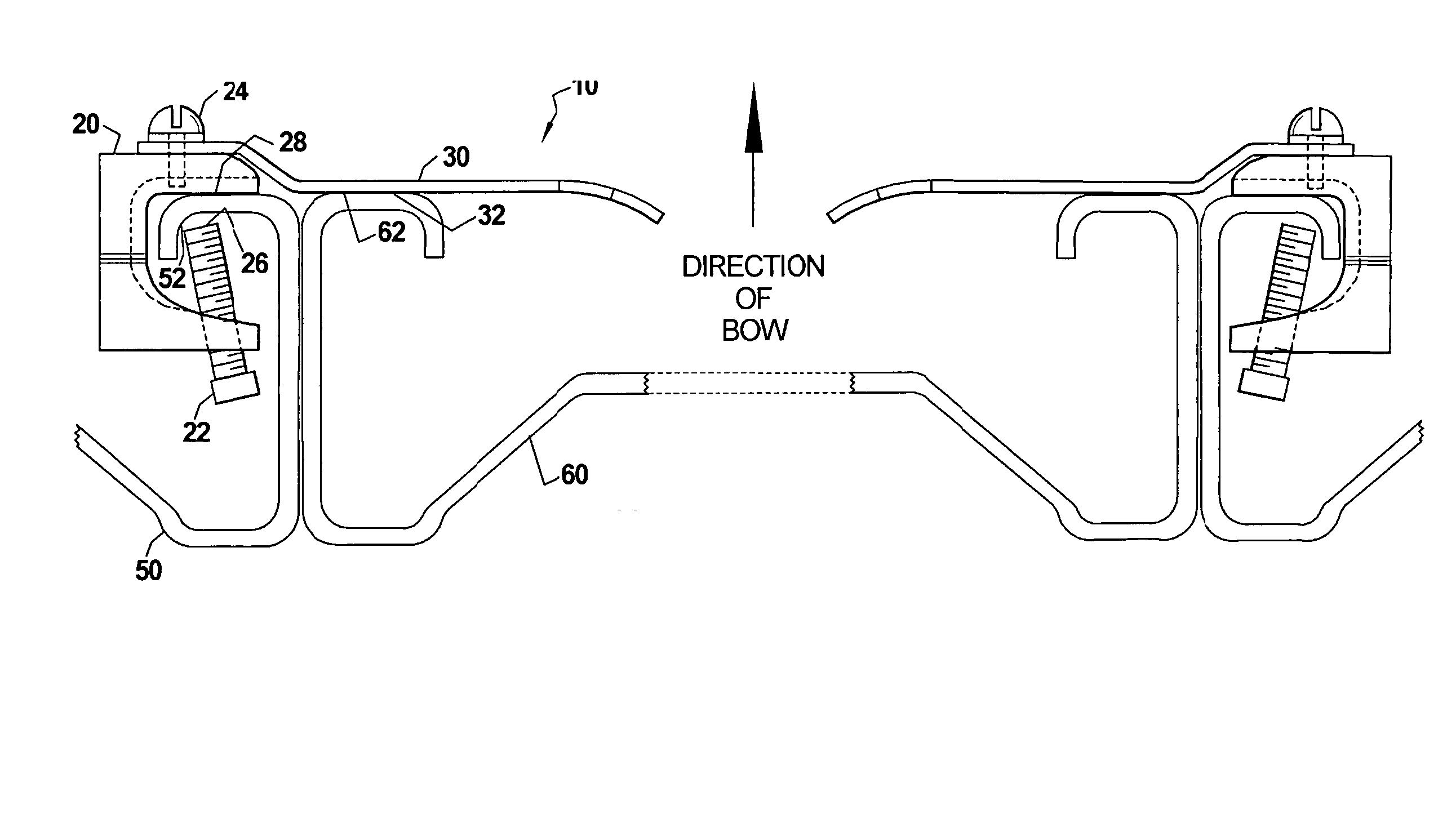
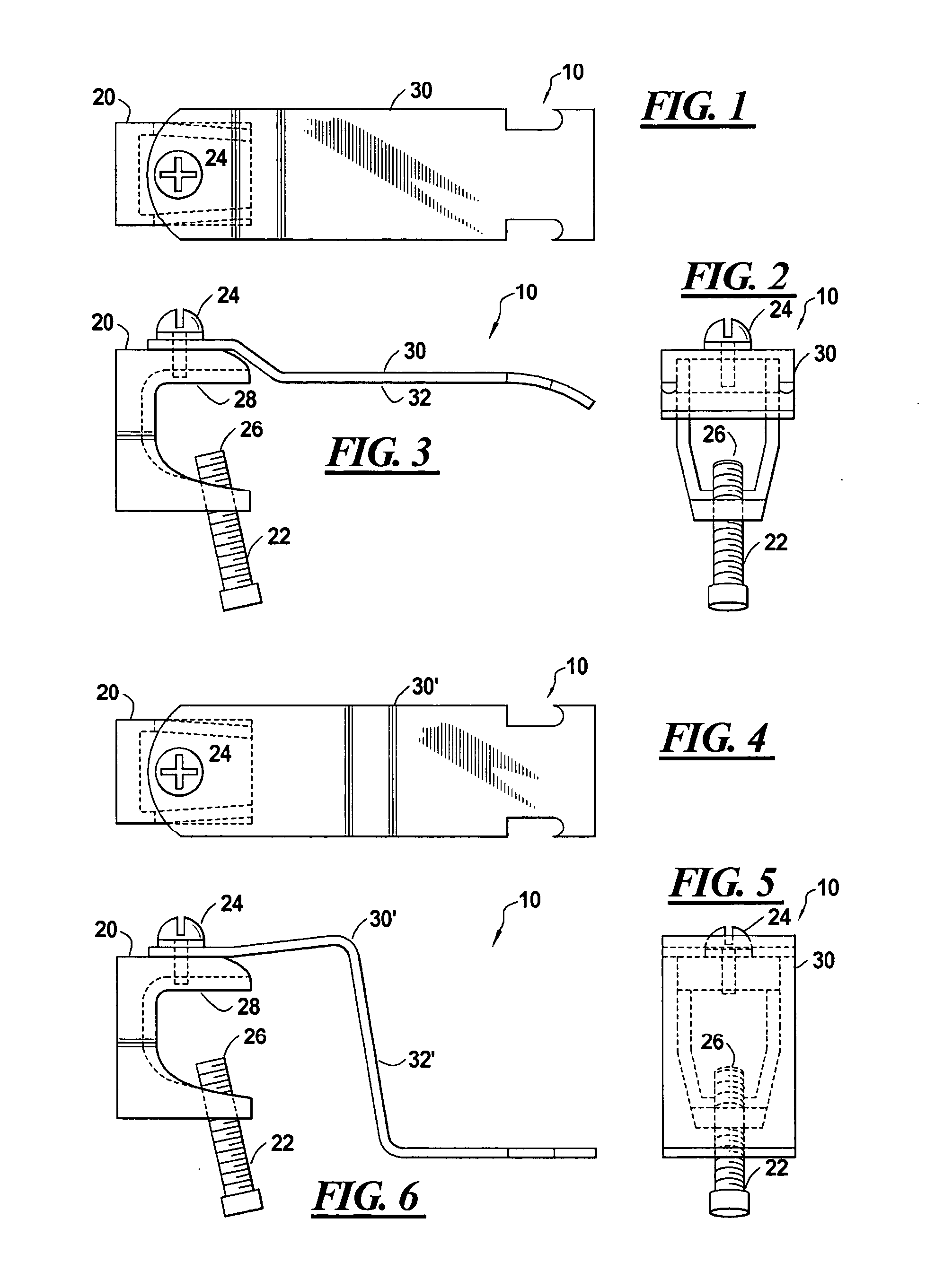
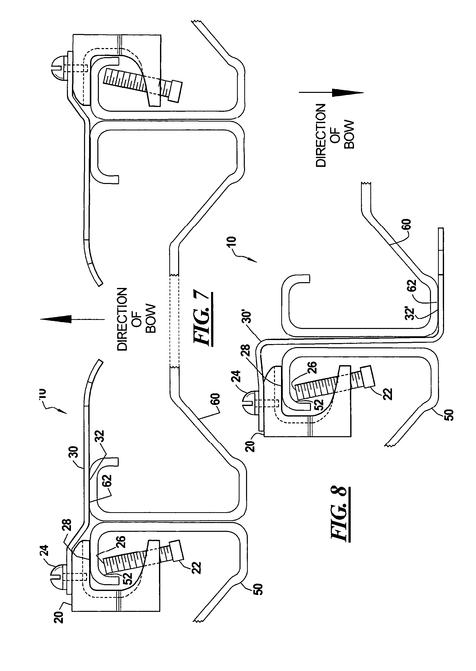
[0028]FIGS. 1-3 illustrate a precipitator collecting plate clip 10 used for straightening or maintaining the straightness of a precipitator collecting plate 60 (FIG. 7); FIG. 1 is a top view, FIG. 2 is a side view, and FIG. 3 is an end view of this embodiment.
[0029] According to the embodiment, the clip 10 comprises a beam clamp 20 (generically, a fastening mechanism) that serves to affix the clip 10 to another element. According to this embodiment, the clamp 20 comprises an anchoring bolt 22 that is used to affix the clip 10 by pinning a portion of the other element between an end of the bolt 26 and a beam clamp mating surface 28, as will be described in greater detail below.
[0030] The claim 20 has a spring-like sheet or plate stiffening element 30 connected to it that is made of a material capable of providing at least some force in a direction perpendicular to a plane defined by a primary surface of the stiffening element 30. The stiffening element 30 is affixed to the clamp 20 ...
second embodiment
[0038]FIGS. 4-6 illustrate a precipitator collecting plate clip 10 used for straightening or maintaining the straightness of a precipitator collecting plate 60′ (FIG. 8); FIG. 4 is a top view, FIG. 6 is a side view, and FIG. 5 is an end view of this embodiment.
[0039] According to the second embodiment, the clip 10 comprises a beam clamp 20 similar to that of the first embodiment that serves to affix the clip 10 to another element. According to this embodiment, the clamp 20 comprises an anchoring bolt 22 that is used to affix the clip 10 by pinning a portion of the other element between an end of the bolt 26 and a beam clamp mating surface 28.
[0040] The claim 20 has a spring-like sheet or plate stiffening element 30′ connected to it that is made of a material capable of providing at least some force in a direction perpendicular to a plane defined by a primary surface of the stiffening element 30. The stiffening element 30′ is affixed to the clamp 20 by, e.g., a fastening screw 24.
[...
PUM
 Abstract
Description
Claims
Application Information