

Cover assembly for a pneumatic spring
a technology of pneumatic springs and assembly parts, applied in the direction of springs/dampers, shock absorbers, vibration dampers, etc., can solve the problems of usable spring space inside the pneumatic spring, high cost of the cover design, and certain conditions, so as to improve the cover for the pneumatic spring, the effect of maximizing the spring space and simple cover
- Summary
- Abstract
- Description
- Claims
- Application Information
AI Technical Summary
Benefits of technology
Problems solved by technology
Method used
Image

Examples
Embodiment Construction
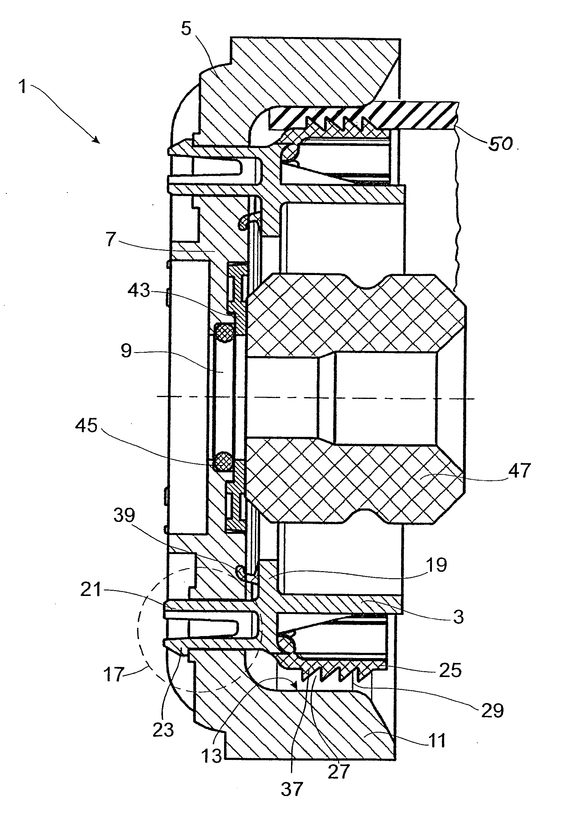
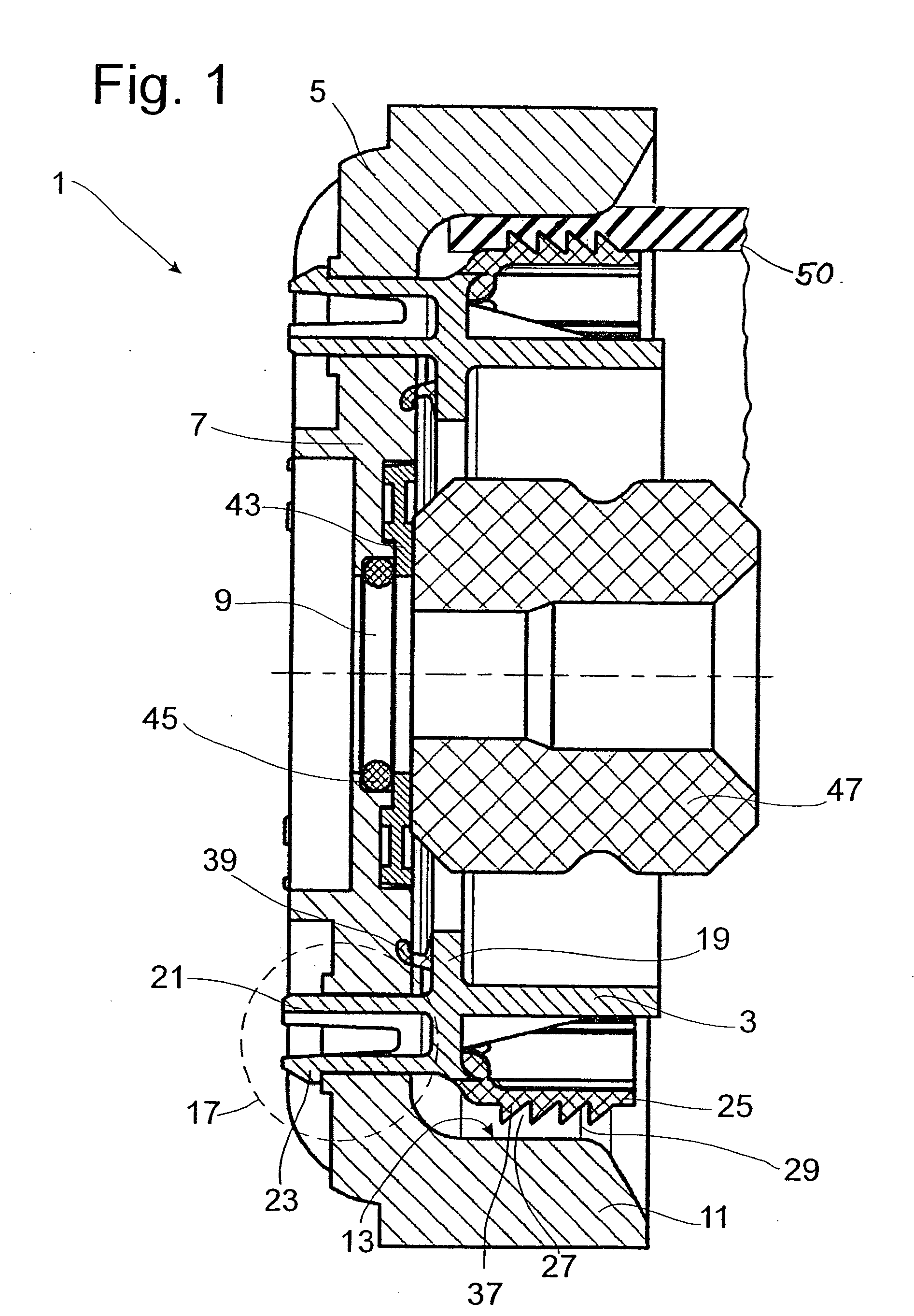
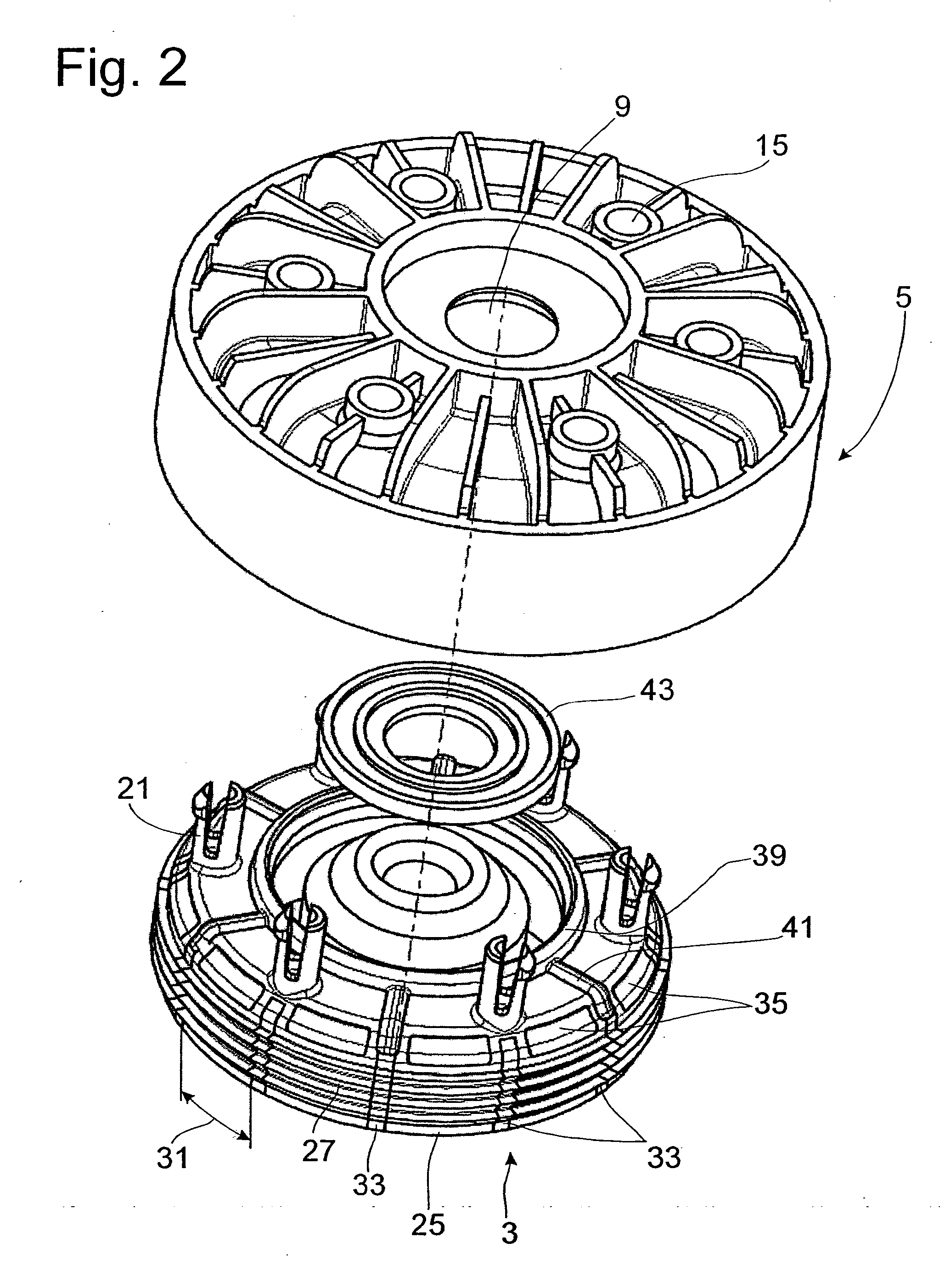
[0017]FIG. 1 shows a cover 1 for a pneumatic spring of the type which can be used in motor vehicles, for example. The design of these springs can be assumed as known. The cover 1 consists, among other things, of an inner cover 3 and an outer cover 5. The outer cover 5 has a cup-shaped cross section with a floor 7 in the form of a circular ring, which possibly has a pass-through opening 9 for a piston rod (not shown) of a vibration damper. Adjacent to the bottom in the axial direction is the circumferential clamping edge 11 with a radially inward-facing clamping surface 13. The clamping edge 11 is designed to have the greatest possible dimensional stability. In addition, the floor 7 has a number of openings 15 (see FIG. 2) for the pin-type connections 17 with the inner cover 3. On the inner cover, several pins 21 project from a floor 19; these pins pass through the openings 15 in the outer cover 5; the pin-type connections thus hold the outer cover and the inner cover together. The p...
PUM
 Abstract
Description
Claims
Application Information