Strap-reel frame

a strap and reel technology, applied in the field of strapstrapstrapstraps, can solve the problems of rewounding by itself, inconvenient subsequent operation of strap drawing, etc., and achieve the effect of convenient pressing and handling, less force, and large area

Inactive Publication Date: 2006-02-16
CHEN HSIU MAN YU
View PDF7 Cites 13 Cited by
  • Summary
  • Abstract
  • Description
  • Claims
  • Application Information

AI Technical Summary

Benefits of technology

[0007] The feature of the invention is the strap-clamping unit assembled on the strap-clamping rod of the frame body. The strap-clamping unit can be actuated to clamp and position a strap, which is drawn outward so as to prevent the strap from rewinding. Additionally, a press member with a comparatively large area is provided on the strap-clamping unit for the convenience of pressing and handling with ease and with less force, and two reel end connectors with a comparatively large diameter can be additionally fixed respectively on the opposite sides of the inner and the outer disc for fitting a strap reel with two comparatively large end holes.

Problems solved by technology

However, the conventional strap-reel frame 10 has no device provided thereon for positioning the strap 21; therefore, when the strap 21 is drawn outward to be used or not, it is likely to be rewound by its own gravitation or tension, and even deformed or dropped to the ground and soiled, always causing much inconvenience to the subsequent operation of strap drawing.

Method used


Image

  • Strap-reel frame
  • Strap-reel frame
  • Strap-reel frame

Examples


Embodiment Construction

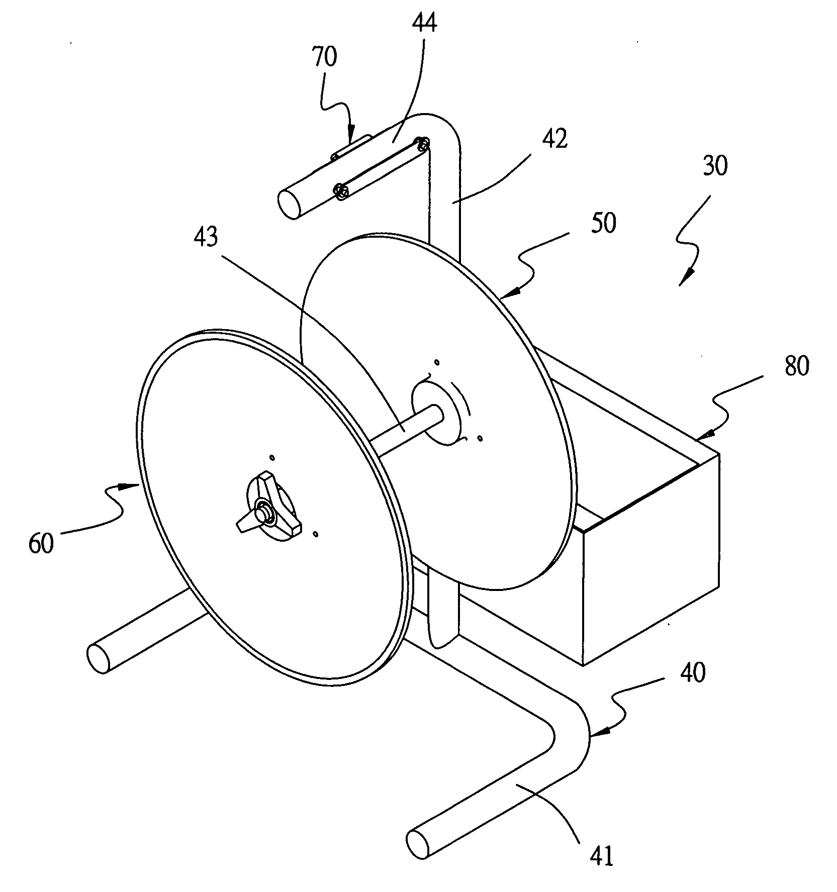
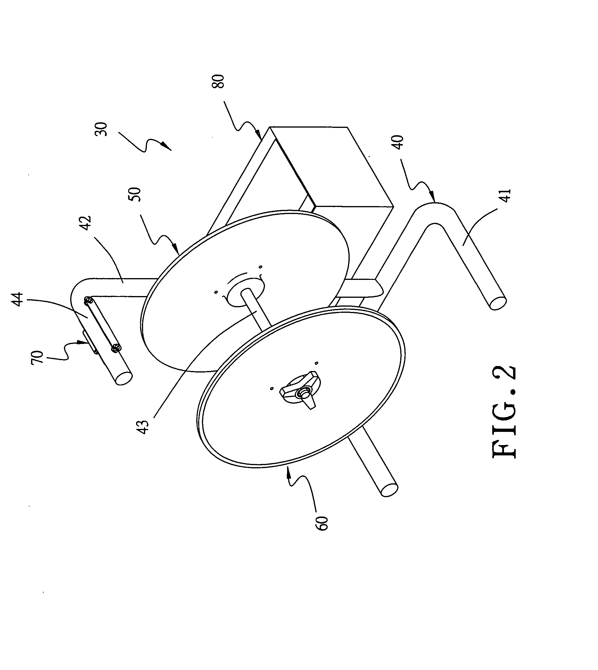
[0016] A preferred embodiment of a strap-reel frame 30 in the present invention, as shown in FIGS. 2, 3 and 4, includes a frame body 40, an inner disc 50, an outer disc 60, a strap-clamping unit 70 and a toolbox 80 combined together.

[0017] The frame body 40 is provided with a U-shaped base rod 41 at the bottom, an upright post 42 extending upward vertically from an intermediate portion of the base rod 41 and a shaft 43 horizontally assembled at an intermediate portion of the upright post 42. The upright post 42 has its upper portion bent horizontally to form a strap-clamping rod 44 having two through holes 441 bored horizontally and diametrically at two preset positions near the intermediate portion.

[0018] The inner disc 50 is bored with a shaft hole 51 in the center for the inner end of the shaft 43 of the frame body 40 to be inserted therethrough. The inner disc 50 further has its central portion formed integral with a hollow columnar projection 52 protruding outward, and has th...


PUM


Abstract

A strap-reel frame includes a frame body having a shaft horizontally provided thereon for fitting an inner disc and an outer disc which respectively have the central portion formed with a columnar projection for fitting the opposite ends of a strap reel. A strap-clamping rod is provided above the shaft of the frame body, having a strap-clamping unit assembled thereon. A strap-passing gap can be formed for a strap to pass therethrough after the press member of the strap-clamping unit is pressed inward and the strap in the strap-passing gap can be clamped in position after the press member is released. In addition, two reel end connectors with a comparatively large diameter can be respectively covered over the two columnar projections and then fixed on the inner and the outer disc for fitting a strap reel.

Description

BACKGROUND OF THE INVENTION [0001] 1. Field of the Invention [0002] This invention relates to a strap-reel frame, particularly to one having functions of strap threading and strap clamping, able to prevent a strap from rewinding or dropping, easy to be handled with less force and applicable for different-sized strap reels to be assembled thereon. [0003] 2. Description of the Prior Art [0004] A conventional strap-reel frame 10, as shown in FIG. 1, includes a frame body 11 having a shaft 111 horizontally assembled thereon for fitting an inner disc 12 and an outer disc 13. The inner disc 12 and the outer disc 13 have their central portions respectively formed with a columnar projection 121, 131 facing each other for pivotally fitting the opposite ends of a strap reel 20 to enable the strap reel 20 to rotate freely between the inner and the outer disc 12, 13 and release the strap 21 wound thereon. [0005] However, the conventional strap-reel frame 10 has no device provided thereon for po...

Claims


Application Information

Patent Timeline
Patent Type & Authority Applications(United States)
IPC IPC(8): B65D85/02
CPCB65H49/305B65H2701/533B65H2701/375B65H59/06
Inventor YU CHEN, HSIU-MAN
Owner CHEN HSIU MAN YU
Why Eureka
Try Eureka