Image forming apparatus

a technology of image forming and forming tubes, which is applied in the direction of electrographic process apparatus, instruments, optics, etc., can solve the problems of deterioration of images when they are transferred, difference in heat capacity of recording materials, and deterioration of images, so as to prevent image deterioration and reduce noise or poor images

Inactive Publication Date: 2006-10-05
CANON KK
View PDF12 Cites 38 Cited by
  • Summary
  • Abstract
  • Description
  • Claims
  • Application Information

AI Technical Summary

Benefits of technology

[0009] It is an object of the present invention to reduce occurrence of noise or poor images, etc., due to switching of conveyance speed of a fixing roller pair, while preventing image deterioration attributable to recording materials that are stretched or bend too much between a transfer roller pair and the fixing roller pair. The present invention includes a transfer means which transfers unfixed images borne by an image bearing member to recording materials, a fixing means which fixes the transferred unfixed images on the recording materials, a loop detecting means which detects a loop of the recording materials to be formed between the transfer means and the fixing means, a recording material detection means which determines that the recording materials have reached to the fixing means, and a control means which controls conveyance speed of the recording materials by the fixing means, wherein based on the detection result of the recording material detection means and the loop detecting means and, length of the recording material, the control means sets the conveyance speed of the fixing means so that when a rear end of the recording material passes through the transfer means after the loop detecting means detected the loop of the recording material, a loop length of the recording material will be set to a lower limit length, and the control means controls the conveyance speed of the fixing means at the set conveyance speed.

Problems solved by technology

However, the heat temporarily removed from the fixing rollers through the fixing process varies depending on amount of deposit of developer that forms unfixed images transferred to the recording materials, the number of passing recording materials per unit time that passes through the fixing roller pair, difference in heat capacity of the recording materials.
Such a difference between the conveyance speeds of the recording materials of the fixing roller pair 105 and the transfer roller pair 103, if any, might result in a deterioration of the image.
Then, the recording materials P that form the oversize loop are pressed hard and scraped against a conveyance guide 120, and the scraping against the conveyance guide 120 might cause image disturbance, thereby resulting in deteriorated images when they are transferred.
Thus, there is a fear that noise would result from the switching of the conveyance speed of the fixing roller pair.
In addition, there is also another fear that poor images might occur, such as image blurring at the transfer portion or fixing nonuniformity at the fixing device, due to periodic minor vibration caused by the switching operation of the conveyance speed.

Method used


Image

  • Image forming apparatus
  • Image forming apparatus
  • Image forming apparatus

Examples


first embodiment

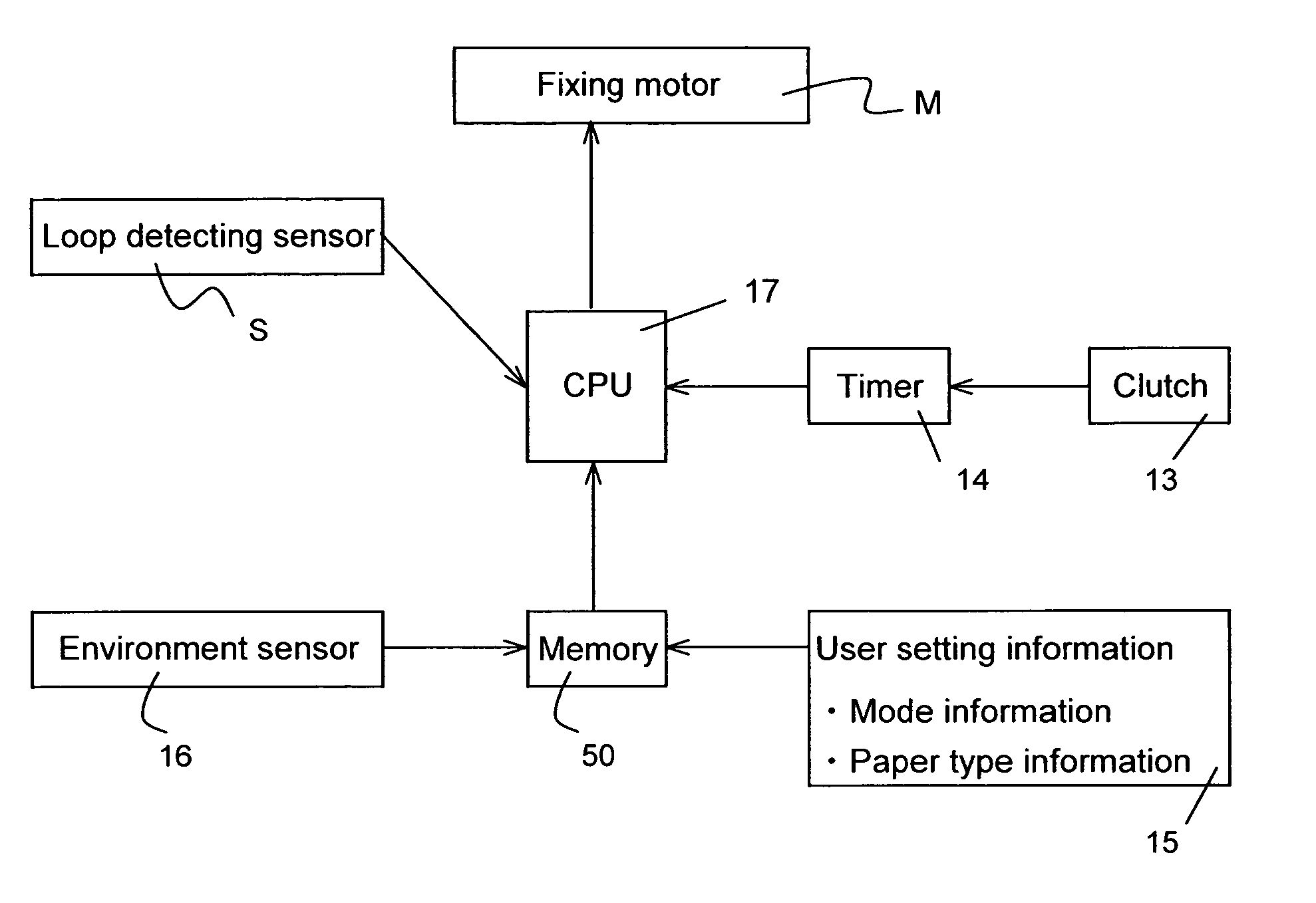
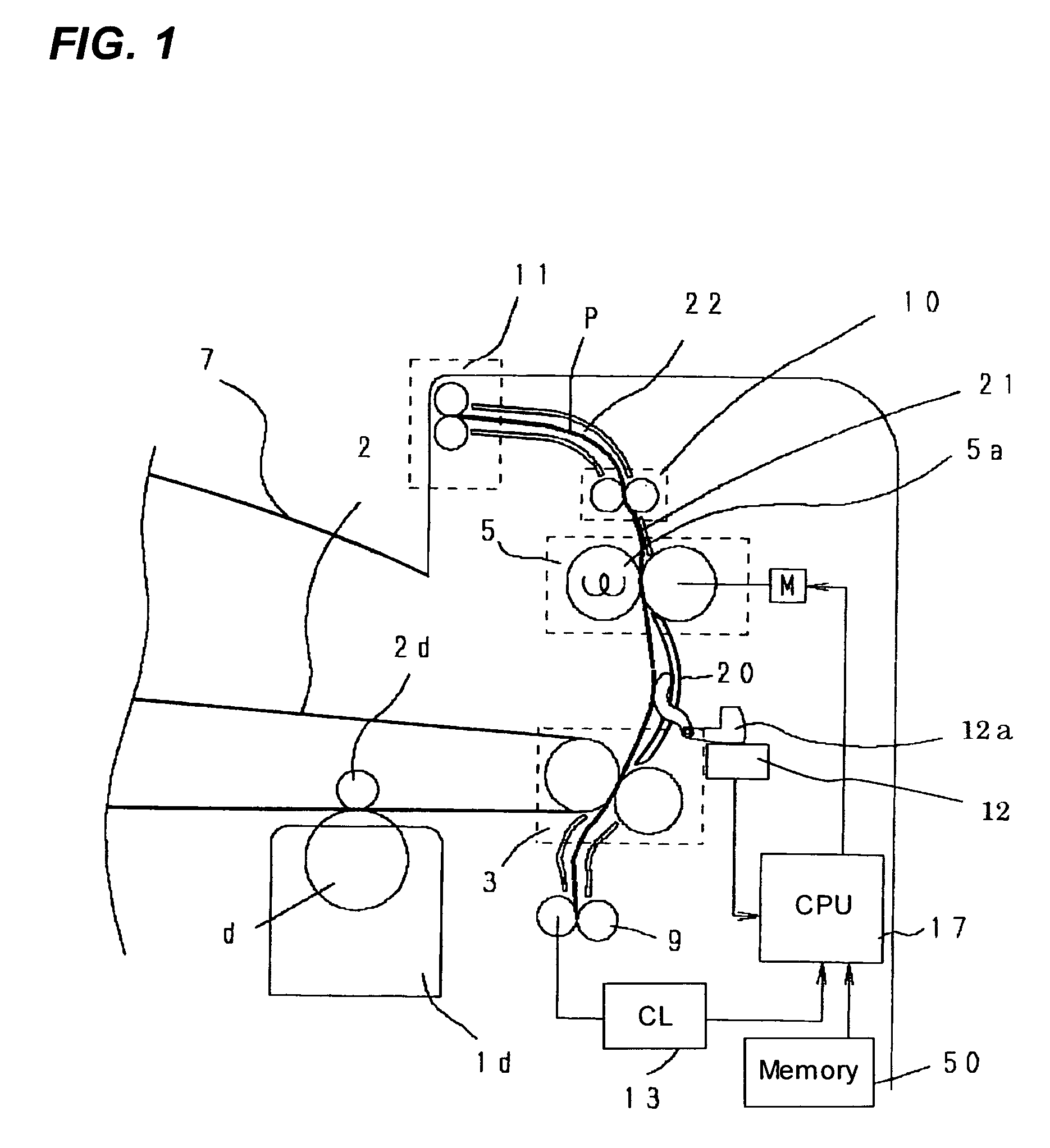
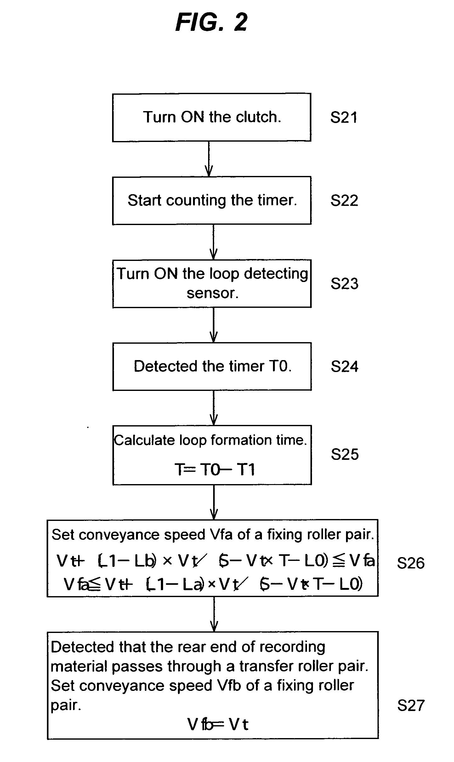
[0025] Here, an image forming apparatus according to a first embodiment of the invention will be described with reference to the drawings. FIG. 1 is a sectional view showing schematic configuration of substantial parts of the image forming apparatus according to the embodiment of the invention. FIG. 2 is a flow chart showing behavior of the image forming apparatus according to the embodiment of the present invention. FIG. 4 is a block diagram of the image forming apparatus according to the embodiment of the present invention. FIG. 4 is a sectional view showing one example of a loop shape between a transfer roller pair and a fixing roller pair. FIG. 5 is a graphic chart showing each setting information on the recording sheet that has been stored in advance in the memory. FIG. 13 is a sectional view of the entire configuration of the image forming apparatus according to the embodiment of the invention.

[0026] First, a schematic configuration of the entire image forming apparatus will ...

second embodiment

[0068] Here, an image forming apparatus according to a second embodiment of the present invention will be described. The image forming apparatus according to the present embodiment is such a configuration that a loop detecting sensor 12 as the loop detecting means also has the operation sensing function for detecting whether or not the operation of conveying recording materials by the fixing roller pair works normally. The loop detecting sensor 12 is capable of detecting operations if the loop detecting sensor detects that the operation does not work normally, for instance, when printing is carried out in out-of-spec conditions, such as operational error by a user, printing on out-of-spec recording materials, or deterioration of parts due to duration, or the like.

[0069] In the following, the image forming apparatus according to the second embodiment will be described in details, with reference to FIG. 9 to FIG. 12. FIG. 9 is a flow chart showing one example of the operation detecti...


PUM


Abstract

Conveyance speed of recording materials by a fixing roller pair can be set to conveyance speed based on detected results of a recording material detection means and a loop detecting sensor, and information on the recording material that has been stored in a memory in advance, wherein the conveyance speed of the fixing roller pair is set so that loop length of the recording material will be a lower limit length, after the loop detecting sensor detects a loop of the recording material, and before the rear end of the recording material passes through the transfer roller pair.

Description

BACKGROUND OF THE INVENTION [0001] 1. Field of the Invention [0002] The present invention relates to an image forming apparatus that transfers unfixed images to recording materials by a transfer means, and fixes the unfixed images on the recording materials by a fixing means. [0003] 2. Description of the Related Art [0004] Conventionally, as shown in FIG. 14, an electrophotographic type image forming apparatus transfers unfixed images borne by an intermediate transfer belt 102 to recording materials P by a transfer roller pair 103, fixes the unfixed images on the recording materials P by a fixing roller pair 105, and discharges the recording materials on which the images have been fixed to a discharge tray 107 outside the apparatus, by a discharge roller pair 111. [0005] The fixing roller pair 105 heat-fixes the unfixed images to the recording materials. However, the heat temporarily removed from the fixing rollers through the fixing process varies depending on amount of deposit of ...

Claims


Application Information

Patent Timeline
Patent Type & Authority Applications(United States)
IPC IPC(8): G03G15/00G03G15/20
CPCG03G15/657G03G2215/00784G03G2215/00603
Inventor KOSHIDA, KOHEISHIRAKATA, JIROTAKEMATSU, KOJIOTAKA, HISASHIMANABE, KEN-ICHIMIYAZAWA, HIDEAKIKOSASA, HIDEAKIYAMANAKA, YUJI
Owner CANON KK
Why Eureka
Try Eureka