Fabric organizer

a fabric organizer and fabric technology, applied in the field of rigid members, can solve the problems of affecting the ability to securely retain the fabric in place, and affecting the organization of fabric. the effect of the organization

Inactive Publication Date: 2006-11-02
HERROD DENIECE
View PDF16 Cites 1 Cited by
  • Summary
  • Abstract
  • Description
  • Claims
  • Application Information

AI Technical Summary

Benefits of technology

[0013] It is therefore an object of the present invention to provide an improved and inexpensive rigid core for retaining the sides of one end of fabric and wrapping the excess fabric around without the need for deforming tension on the material. It is a further embodiment of the present invention to provide a structure that is durable, proportionate to common fabric width, and facilitates organization of fabric.

Problems solved by technology

Many different configurations of this type of inner core member have been practiced, but in some instances, the fabric may fall off the board or become unwound through handling.
Further, retaining the material through tensioning of the material may distort the material itself.
Therefore, as the amount of fabric wrapped around the board decreases, the ability to securedly retain the fabric in place diminishes.
All retaining force in imparted by tension in the material, again presenting the same problem as the Doyere patent.
While a tongue member is punched or slit out of the sheet material of the body for frictionally holding an identification tag, the tongue member is not sufficient for retaining various material thickness.
Further, the flexibility of the body does not provide sufficient rigidity.
However, this invention does not present an economical option to providing a rigid, inner core member.

Method used


Image

  • Fabric organizer
  • Fabric organizer
  • Fabric organizer

Examples


Embodiment Construction

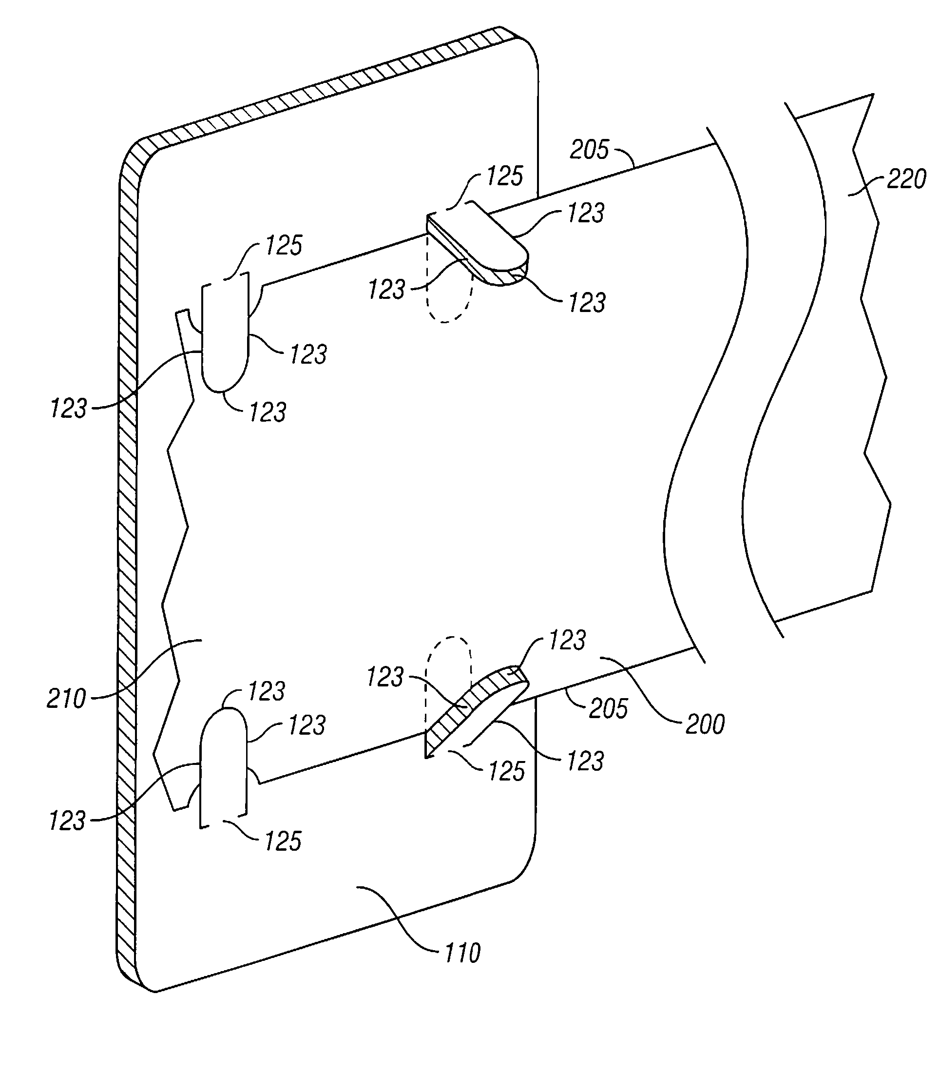
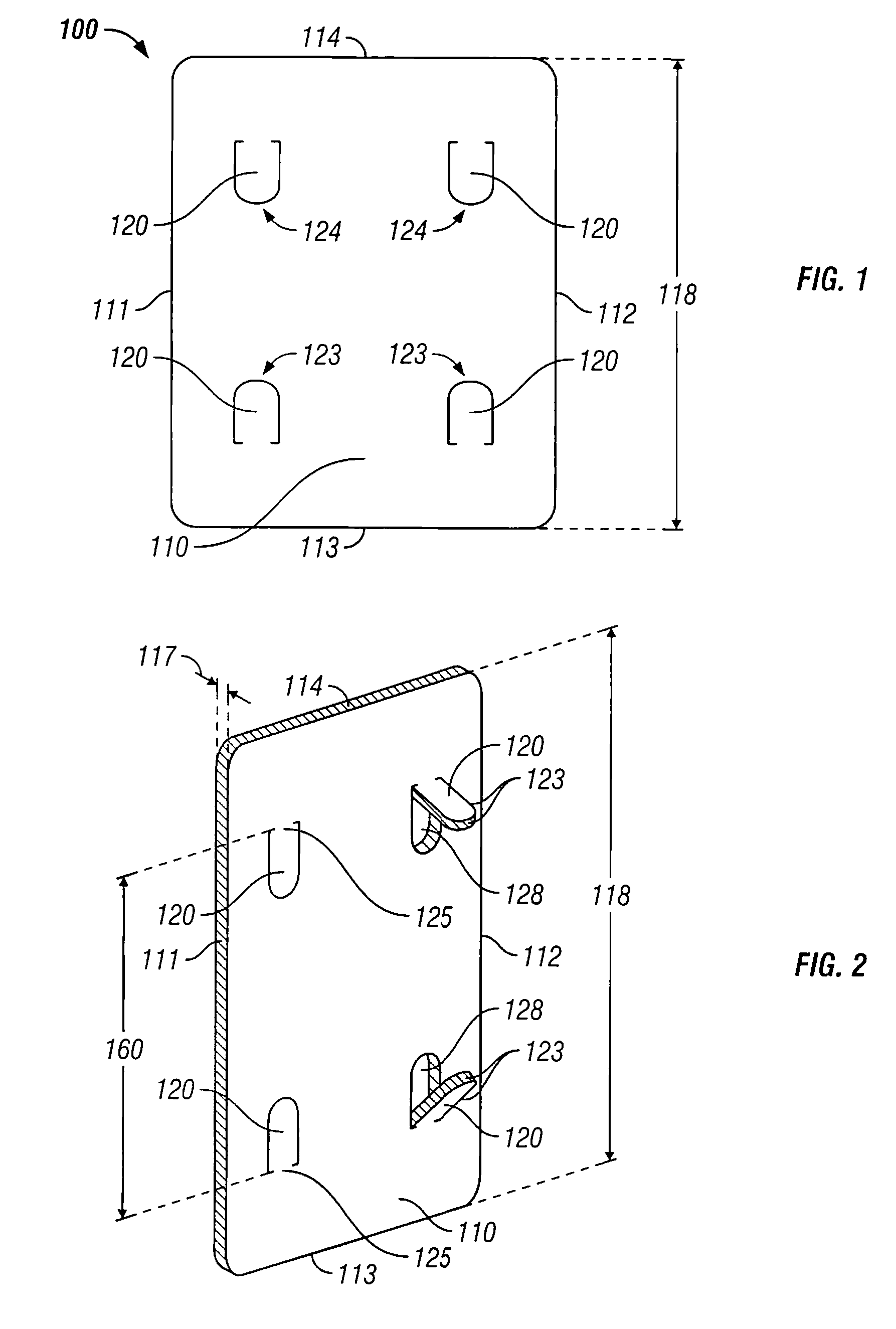
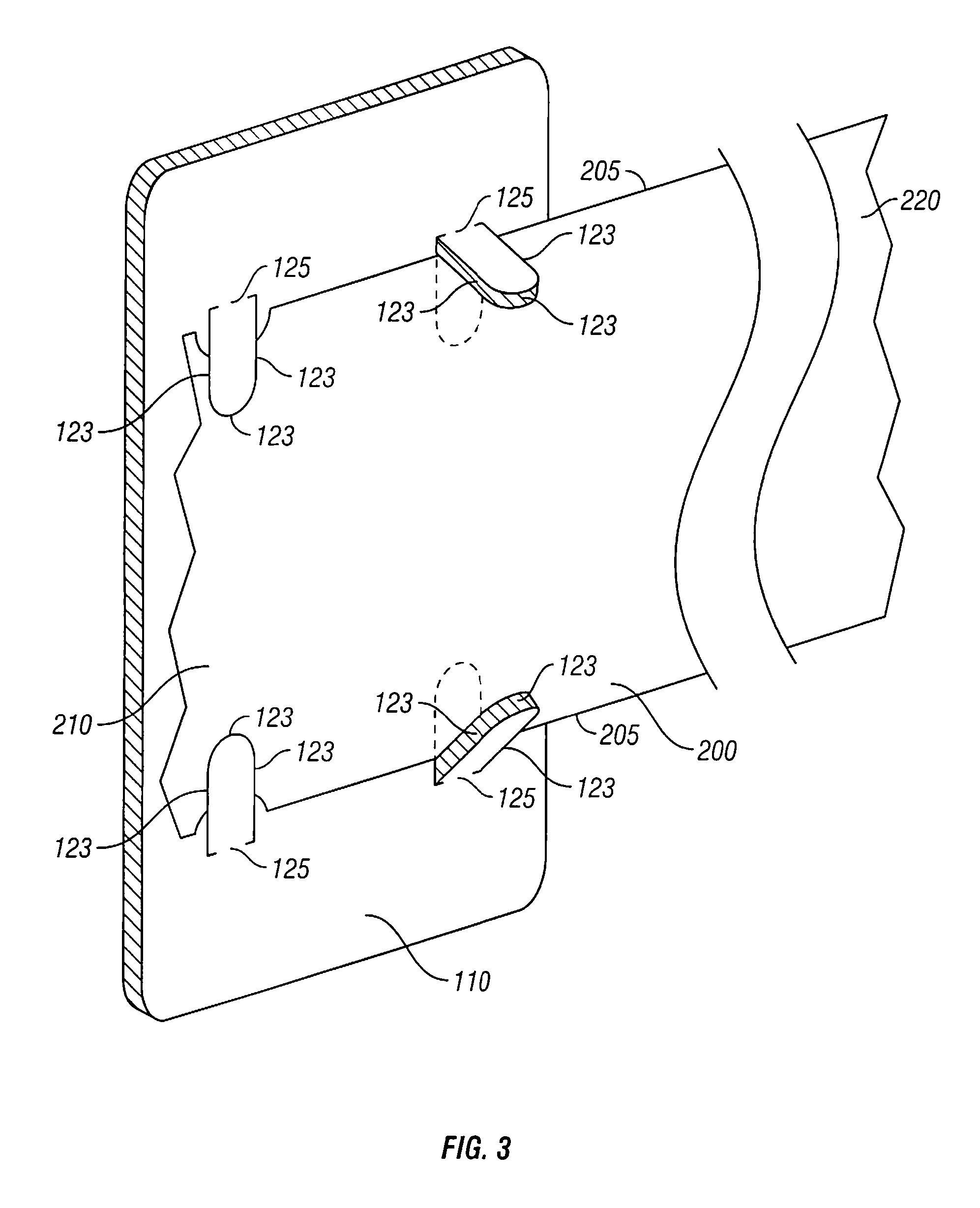
[0022]FIG. 1 depicts the preferred embodiment of fabric organizer 100. Fabric organizer 100 comprises body 110 and a plurality of fabric retaining tabs 120.

[0023] Referring to FIG. 2, body 110 is preferably elongated, thereby providing sufficient surface area for extending fabric 200 (seen in FIG. 3), whether folded or unfolded, so long as less than the distance between retaining tabs connected segment 125 but greater than the distance between fabric retaining tabs 120 and longitudinally wrapping fabric 200 around body 110. Body 110 should have a body sufficient to provide rigid support. Body 110 is preferably a durable, lightweight material, such as plastic or similar material known in the art, sufficiently thick to provide rigidity or having an internal structure to provide such rigidity. The perimeter of body 110 is defined by first side edge 111, second side edge 112, bottom edge 113 and top edge 114. Body 110 is preferably planar, which allows for the efficient storage of mult...


PUM


Abstract

The fabric organizer comprises a planar, elongated body, with at least two retaining tabs opposedly aligned. The retaining tabs are generally U-shaped and are integrally formed with the body. The retaining tabs are frictionally engageable with the body. The free end of the retaining tabs are disengaged from the body, thereby creating a cavity for receiving fabric. One end of the fabric is extended across one side of the body, the retaining tabs are frictionally engaged with the body, thereby retaining one end of the fabric in place.

Description

CROSS-REFERENCE TO RELATED APPLICATIONS [0001] This application claims the benefit of U.S. Provisional Patent Application No. 60 / 676,215 entitled, “Fabric Organizer,” filed on Apr. 29, 2005 in the United States Patent and Trademark Office.STATEMENT REGARDING FEDERALLY SPONSORED RESEARCH OR DEVELOPMENT [0002] Not Applicable. BACKGROUND OF THE INVENTION [0003] 1. Field of the Invention [0004] The present invention relates to a device for organizing and holding fabric in position, and more particularly to a rigid member for frictionally retaining the two sides of fabric and providing a core for wrapping the fabric around without the necessity of tensioning the fabric. [0005] 2. Description of the Related Art [0006] In handling and storing of fabric, the general practice has been to incorporate a rigid inner member to use as an axis for wrapping the fabric around. Previously, the fabric was retained about the inner member by tension of the material as the material is wrapped about the m...

Claims


Application Information

Patent Timeline
Patent Type & Authority Applications(United States)
IPC IPC(8): B65D85/04B65H18/28B65H75/06
CPCB65D85/672
Inventor HERROD, DENIECE
Owner HERROD DENIECE
Why Eureka
Try Eureka