Tube finning machine and method

a technology of finning machine and tube, which is applied in the direction of heat exchange apparatus, metal-working apparatus, metal-working apparatus, etc., can solve the problems of compromising a bit on heat exchange capability, a tube which is more likely to buckle or deform, etc., and achieves the effect of reducing or compromising heat exchange capability

Inactive Publication Date: 2006-11-30
PIERCE DAVID BLAND
View PDF2 Cites 3 Cited by
  • Summary
  • Abstract
  • Description
  • Claims
  • Application Information

AI Technical Summary

Benefits of technology

[0012] The present invention seeks to reduce or avoid the problems associated with the prior art machines and methods described above, and in particular to provide a tub...

Problems solved by technology

Satisfying the former desire results in a tube which is more likely to buckle or deform when the force needed to apply the fins to th...

Method used


Image

  • Tube finning machine and method
  • Tube finning machine and method

Examples


Embodiment Construction

[0040] For ease of reference, in the following description similar components are given the same reference numeral, notwithstanding the description of different embodiments.

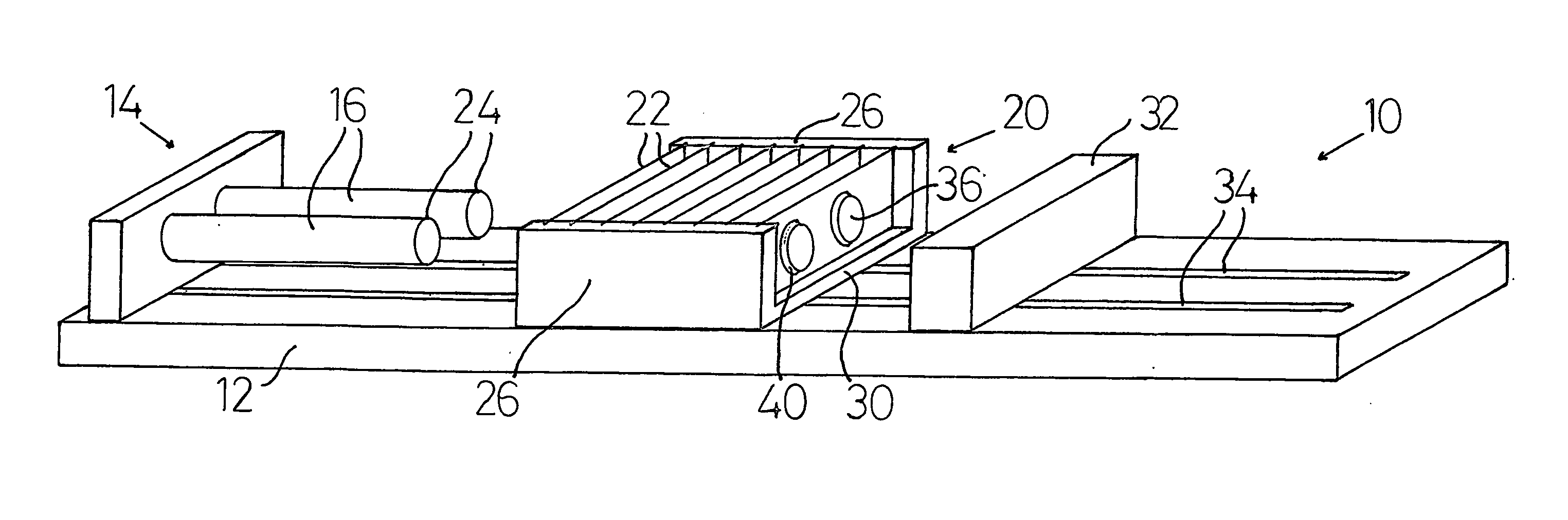
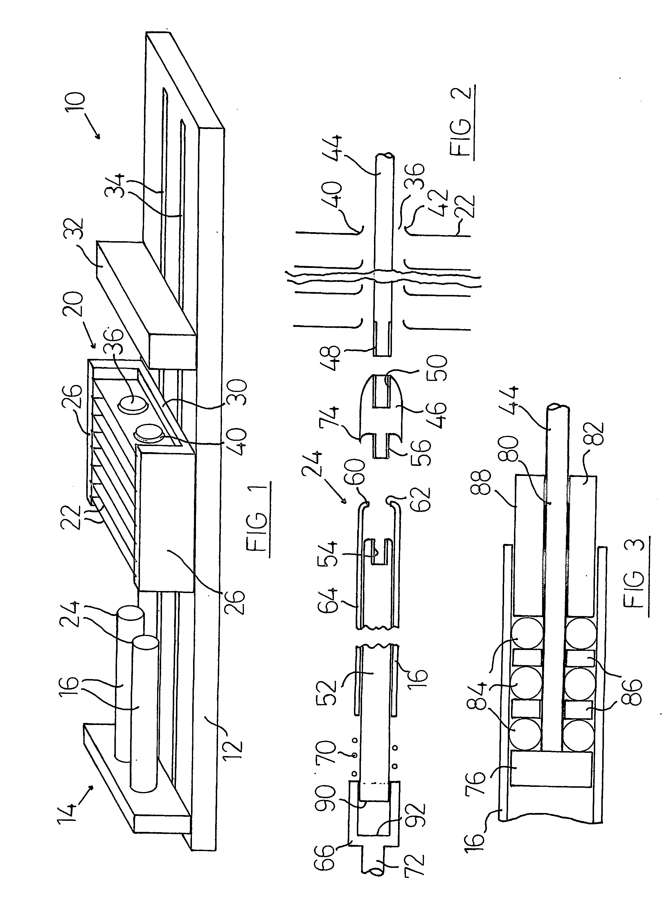
[0041] The machine 10 of FIG. 1 has a base 12, a first mounting means 14 by which two tubes 16 are mounted upon the base, and a second mounting means 20 by which a number of fins 22 are mounted upon the base 12.

[0042] As is typical in tube finning machines, the tubes 16 are mounted in cantilever by the first mounting means 14, so that each tube has a free end 24 to receive the fins 22. A part of one suitable first mounting means is described in relation to FIG. 2 below, but it will be understood that many different means of mounting the tubes 16 to the base 12 could be used.

[0043] As is also typical in tube finning machines, the second mounting means 20 comprises a cartridge which can accommodate the required number of fins. The cartridge 20 has a number of slots formed into its side walls 26 and base 30, each...


PUM

PropertyMeasurementUnit
Forceaaaaaaaaaa
Tensionaaaaaaaaaa

Abstract

This invention relates to a tube finning machine (10) and to a method of use thereof. Typically, the finned tubes will be for use in heat exchangers. In the present invention, the machine (10) has tensioning means (32, 44) for applying tension to the tubes (16) during the finning process, tension in the tubes reducing the likelihood that the tubes will buckle or deform during the process. Also, the invention discloses the use of a solid material introduced between the fins (22) to support the fins during the finning process, the solid material being removed after completion of the process. The solid material can be a granular material, or it can be a continuous material introduced (and removed) in its liquid state.

Description

FIELD OF THE INVENTION [0001] This invention relates to a tube finning machine and to a method of use thereof. [0002] Typically, the finned tubes will be for use in heat exchangers, and the following description relates primarily to such use. However, the use of the machine and method for other applications is not thereby excluded. BACKGROUND TO THE INVENTION [0003] Often it is necessary to cool a working fluid, and it is known for this purpose to use a heat exchanger. Heat exchangers often comprise one or more metallic tubes suspended between two tube plates. Usually, the working fluid to be cooled, which may for example be water or oil, flows through the tubes, whilst the coolant passes around and between those tubes, the working fluid giving up its latent heat to the tubes and thus to the coolant. [0004] The effective surface area of a tube can be enlarged in order to increase the heat transfer, as by the addition of one or more annular extended surface members or fins in thermal...

Claims


Application Information

Patent Timeline
IPC IPC(8): B23P15/26B21D53/08B23P19/02
CPCB21D53/085B23P15/26B23P19/022Y10T29/53122Y10T29/4938Y10T29/49378Y10T29/53117
Inventor PIERCE, DAVID BLAND
Owner PIERCE DAVID BLAND
Why Eureka
Try Eureka