Cable laying configuration

Inactive Publication Date: 2007-04-05
CABLERUNNER AUSTRIA GMBH & CO KG +1
View PDF6 Cites 22 Cited by
  • Summary
  • Abstract
  • Description
  • Claims
  • Application Information

AI Technical Summary

Benefits of technology

[0011] It is accordingly an object of the invention to provide a cable laying configuration which overcome the above-mentioned disadvantages of the prior art devices and methods of this general

Problems solved by technology

Even in those fields with few obstacles, the lines or cables provided for the noted purposes are no longer laid to a large extent over trouble-prone overhead lines in the country, but, if possible, underground whereby, although the excavation and laying work required for this is relatively expensive, it is hampered relatively l

Method used


Image

  • Cable laying configuration
  • Cable laying configuration
  • Cable laying configuration

Examples


Embodiment Construction

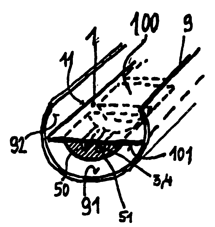
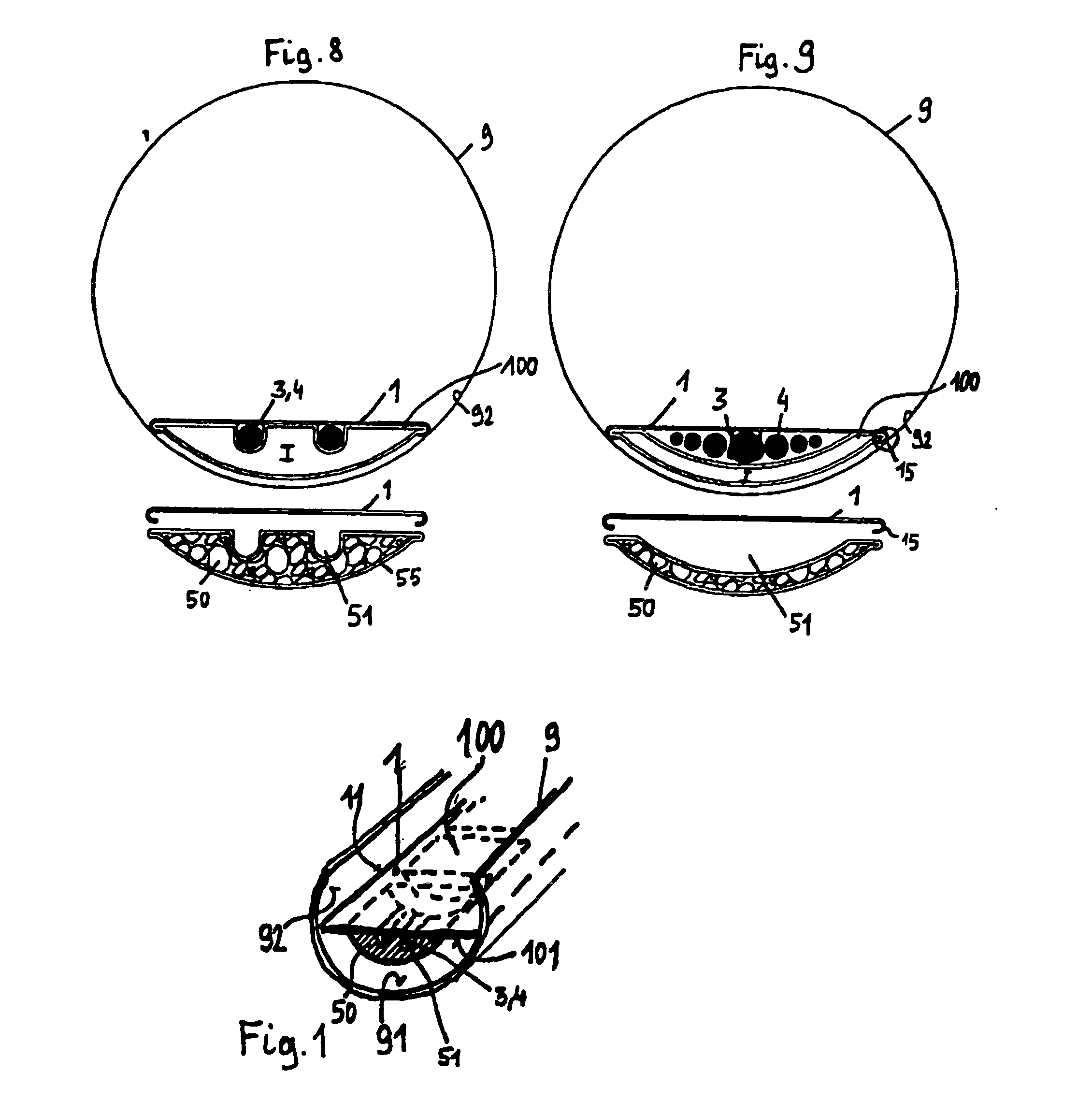
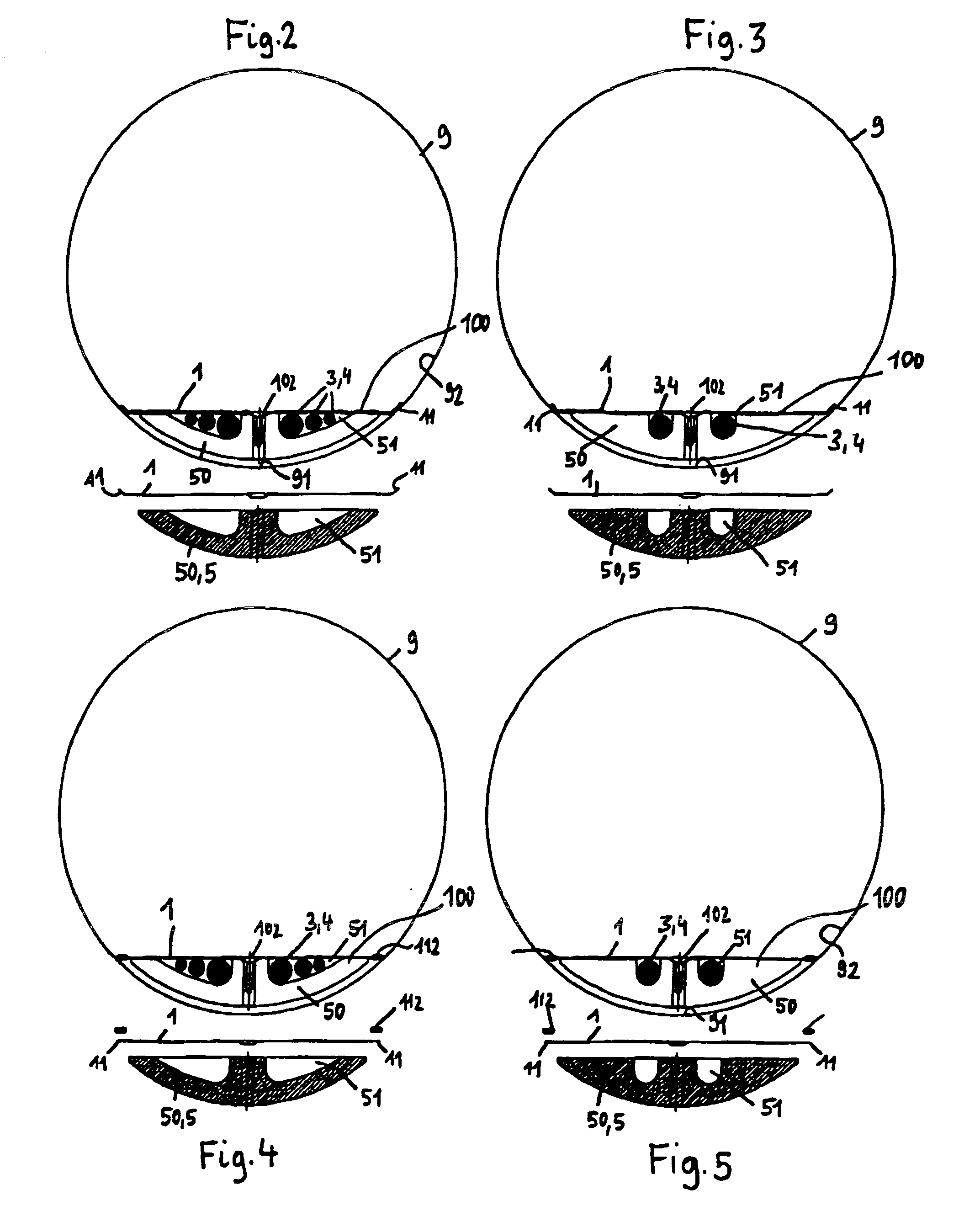
[0072] Referring now to the figures of the drawing in detail and first, particularly, to FIG. 1 thereof, there is shown how a carrier plate 1, e.g. of high-grade steel, is drawn into a sewer pipe 9 in a cable-laying configuration 100 according to the invention in such a way that it braces itself with its lateral edges 11 on a concave inner wall surface 92 of a pipe channel on both sides. A cable 4, which is optionally held or guided in a cable support profile 3, is disposed on an underside 101 of the carrier band 1 running along it, and, furthermore, a series of weighting elements 50, e.g. made of heavy concrete, which are spaced from one another and in a cylinder-segment like form, are attached to the underside 101, e.g. by screws 102 which on the whole form a “discontinuous” weighting body 5.

[0073] The weighting elements 50 have a correspondingly shaped groove-like recess 51 where the cable 4 runs. The weighting elements 50 are substantially formed analogously to a channel base 9...


PUM


Abstract

A laid cable configuration contains cables, preferably electric cables, data and information transport cables and/or control cables, in particular fiber optic cables, and fluid transport tubes and is to be disposed in galleries, tunnels, shafts, pipes, channels or the like, in particular water and/or waste-water guiding systems. The configuration contains at least one cable which is to be laid, which can be unwound from a drum from the region of an opening providing access to an installation shaft or access shaft or the like toward the respective pipe, channel or the like, or drawn or fixed in a stationary manner in the pipe, channel or the like. Accordingly, a stationary positioning of the cable and/or the laid cable configuration, which is optionally maintained by a cable support, is obtained and ensured by the force of gravity and the frictional fit thus arising.

Description

CROSS-REFERENCE TO RELATED APPLICATIONS [0001] This is a continuing application, under 35 U.S.C. §120, of copending international application No. PCT / AT2005 / 000079, filed Mar. 8, 2005, which designated the United States; this application also claims the priority, under 35 U.S.C. §119, of Austrian patent application Nos. A 446 / 2004, A 1081 / 2004, and A 1801 / 2004, respectively filed Mar. 12, 2004, Jun. 24, 2004, and Oct. 25, 2004; the prior applications are herewith incorporated by reference in their entirety.BACKGROUND OF THE INVENTION [0002] The present invention relates to a new cable laying configuration, preferably electric cables, data and information transport cables and / or control cables, in particular fiber optic cables, fluid transport tubes or the like in galleries, tunnels, shafts, pipes, channels or the like, in particular water and / or waste-water guiding systems. The configuration contains at least one cable which is to be laid, which can be unwound from a drum from the r...

Claims


Application Information

Patent Timeline
IPC IPC(8): F16L7/00F16L3/223G02B6/50H02G1/08H02G9/06
CPCF16L3/223F16L7/00G02B6/508H02G1/08H02G1/088H02G9/06
Inventor KADRNOSKA, HELMUTREISS, GERHARD
Owner CABLERUNNER AUSTRIA GMBH & CO KG
Why Eureka
Try Eureka