Cable laying configuration

a cable and configuration technology, applied in the direction of power cables, cables, insulated conductors, etc., can solve the problems of high material and manipulation expenditure, difficult to lay cables and lines of this type under the surface in congested city areas, and relatively high excavation and laying costs

Inactive Publication Date: 2009-04-07
CABLERUNNER AUSTRIA GMBH & CO KG +1
View PDF10 Cites 45 Cited by
  • Summary
  • Abstract
  • Description
  • Claims
  • Application Information

AI Technical Summary

Benefits of technology

[0011]It is accordingly an object of the invention to provide a cable laying configuration which overcome the above-mentioned disadvantages of the prior art devices and methods of this general type, which requires a relatively low material and manipulation expenditure when positioning stationary cables (substantially equivalent to fastening the cables) in pipes, channels and the like.
[0012]Therefore, the object of the present invention is a novel cable laying configuration of laying cables in pipes, channels or the like of the aforementioned type which is characterized in that a stationary positioning of the cables and / or the laying configuration which is optionally maintained by a cable support, is obtained and ensured by the force of gravity and the frictional fit thus arising. It is especially advantageous if the configuration contains a flexible and / or articulated carrier band which can be pulled into the pipe or into the channel, disposed at a distance from the bottom of the pipe, the channel sole or the like and which can preferably be placed against the inner wall surface of the pipe or channel, adjoining both sides with its lateral edges, optionally forming a substantially flat second sole in the pipe or channel disposed above the pipe base and / or channel sole. On an underside pointing to the pipe base and / or channel sole, cable supports are provided for mounting the cable. At least one continuous weighting body is provided on the pipe base and / or channel sole and prevent the cable from rising in the water, waste water or the like in the pipe and / or channel or flowing through them, or a multitude or plurality of weighting elements spaced from one another. Within the scope of the present invention, an especially stable cable laid configuration is provided if the weighting body or the weighting elements lies / lie on the channel sole in which it is provided that the weighting body or the weighting elements is / are suspended on the carrier band supported on both sides on the pipe wall, attached to the underside thereof, and the carrier band(s) is / are disposed pressed against the inner wall surfaces of the pipe and / or channel with its lateral edges.

Problems solved by technology

Even in those fields with few obstacles, the lines or cables provided for the noted purposes are no longer laid to a large extent over trouble-prone overhead lines in the country, but, if possible, underground whereby, although the excavation and laying work required for this is relatively expensive, it is hampered relatively little by other underground installations.
Laying cables and lines of this type under the surface in congested city areas is much more difficult, whereby the aspect of traffic obstructions due to excavation work should be noted here as a substantial disadvantage, in addition to the abundance of existing underground installations.

Method used


Image

  • Cable laying configuration
  • Cable laying configuration
  • Cable laying configuration

Examples


Embodiment Construction

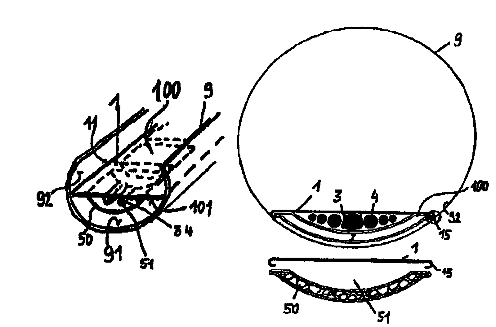
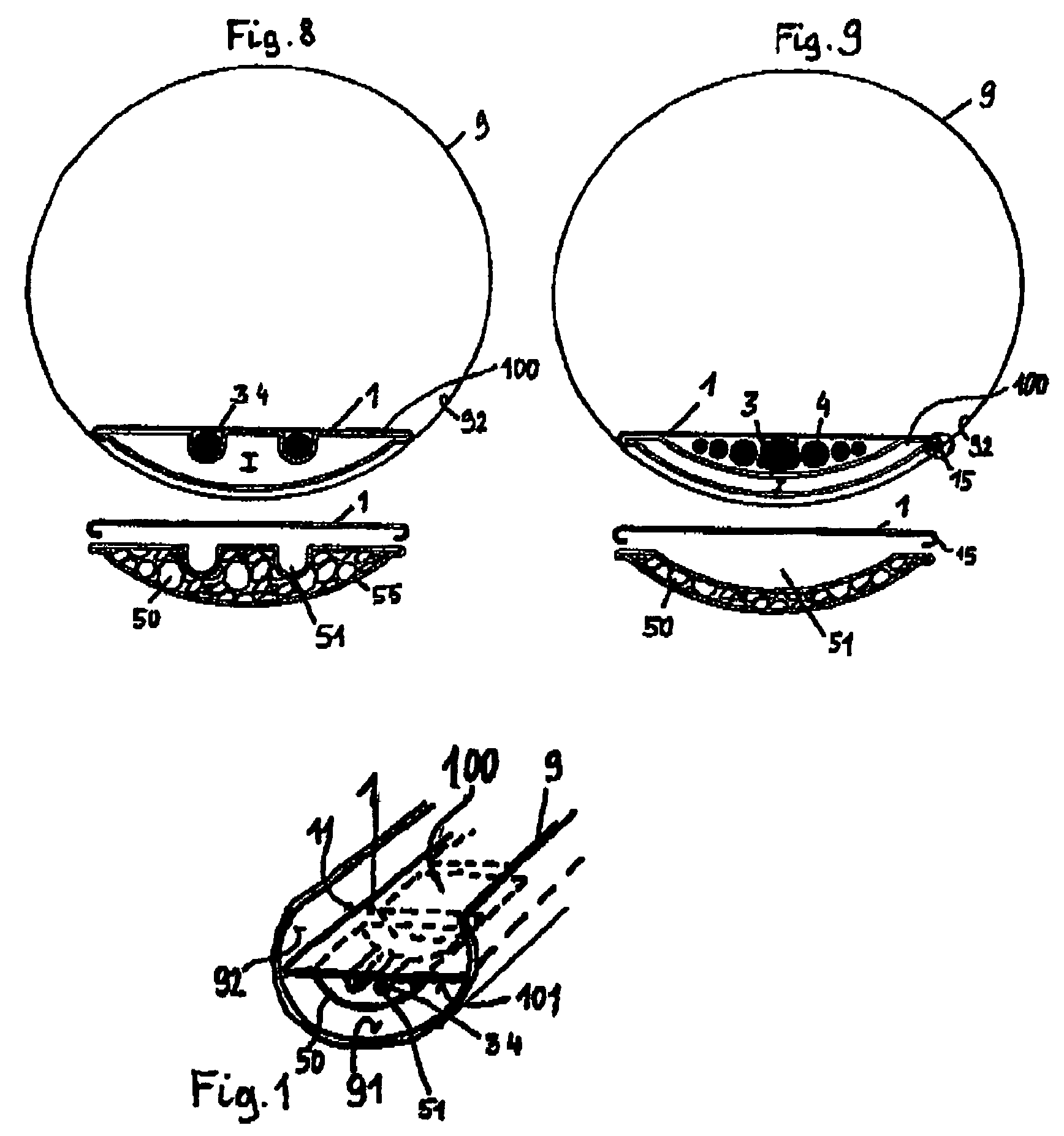
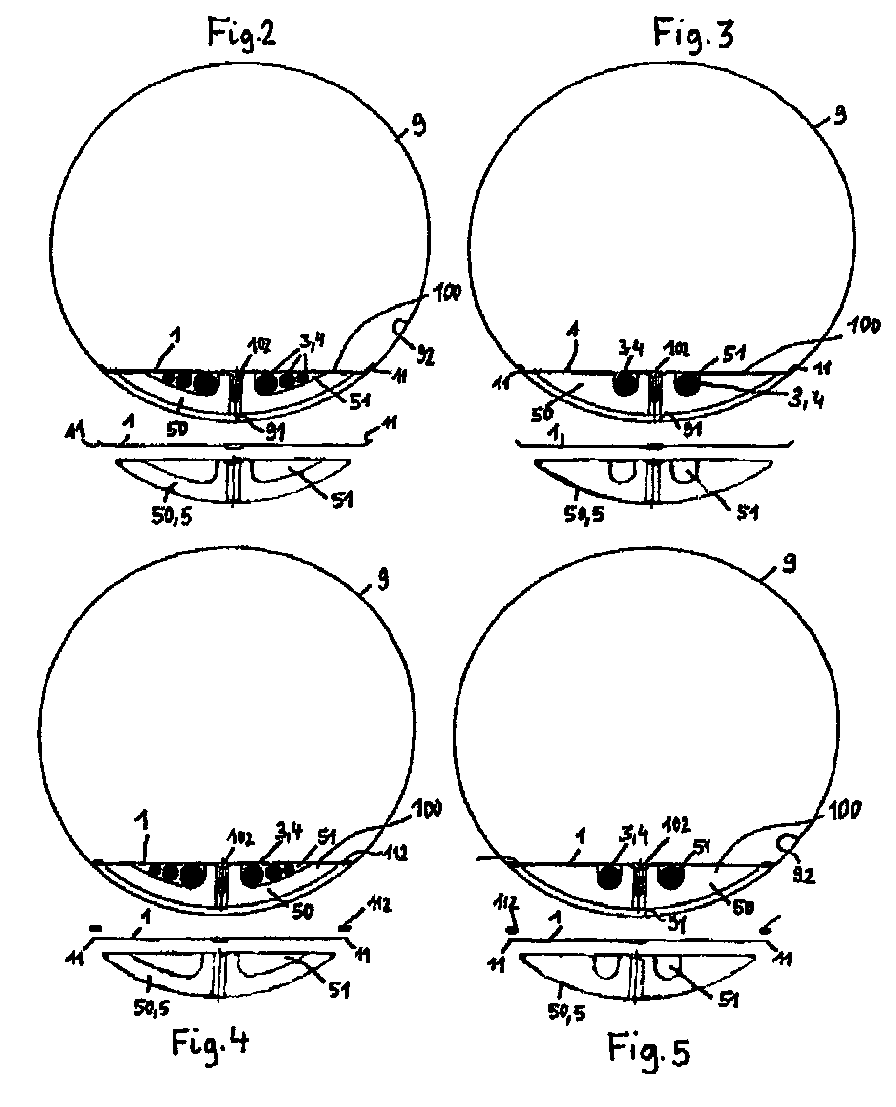
[0073]Referring now to the figures of the drawing in detail and first, particularly, to FIG. 1 thereof, there is shown how a carrier plate 1, e.g. of high-grade steel, is drawn into a sewer pipe 9 in a cable-laying configuration 100 according to the invention in such a way that it braces itself with its lateral edges 11 on a concave inner wall surface 92 of a pipe channel on both sides. A cable 4, which is optionally held or guided in a cable support profile 3, is disposed on an underside 101 of the carrier band 1 running along it, and, furthermore, a series of weighting elements 50, e.g. made of heavy concrete, which are spaced from one another and in a cylinder-segment like form, are attached to the underside 101, e.g. by screws 102 which on the whole form a “discontinuous” weighting body 5.

[0074]The weighting elements 50 have a correspondingly shaped groove-like recess 51 where the cable 4 runs. The weighting elements 50 are substantially formed analogously to a channel base 91 b...


PUM

PropertyMeasurementUnit
densityaaaaaaaaaa
densityaaaaaaaaaa
distancesaaaaaaaaaa

Abstract

A laid cable configuration contains cables, preferably electric cables, data and information transport cables and / or control cables, in particular fiber optic cables, and fluid transport tubes and is to be disposed in galleries, tunnels, shafts, pipes, channels or the like, in particular water and / or waste-water guiding systems. The configuration contains at least one cable which is to be laid, which can be unwound from a drum from the region of an opening providing access to an installation shaft or access shaft toward the respective pipe or channel, or drawn or fixed in a stationary manner in the pipe, channel or the like. The configuration includes a flexible and / or articulated carrier band having lateral edges that are laid against an inner wall surface of the pipe or the channel. A weighting body is suspended from the carrier band.

Description

CROSS-REFERENCE TO RELATED APPLICATIONS[0001]This is a continuing application, under 35 U.S.C. §120, of copending international application No. PCT / AT2005 / 000079, filed Mar. 8, 2005, which designated the United States; this application also claims the priority, under 35 U.S.C. §119, of Austrian patent application Nos. A 446 / 2004, A 1081 / 2004, and A 1801 / 2004, respectively filed Mar. 12, 2004, Jun. 24, 2004, and Oct. 25, 2004; the prior applications are herewith incorporated by reference in their entirety.BACKGROUND OF THE INVENTION[0002]The present invention relates to a new cable laying configuration, preferably electric cables, data and information transport cables and / or control cables, in particular fiber optic cables, fluid transport tubes or the like in galleries, tunnels, shafts, pipes, channels or the like, in particular water and / or waste-water guiding systems. The configuration contains at least one cable which is to be laid, which can be unwound from a drum from the regio...

Claims


Application Information

Patent Timeline
Patent Type & Authority Patents(United States)
IPC IPC(8): H01B7/00F16L3/223F16L7/00G02B6/50H02G1/08H02G9/06
CPCF16L3/223F16L7/00G02B6/508H02G1/08H02G1/088H02G9/06
Inventor KADRNOSKA, HELMUTREISS, GERHARD
Owner CABLERUNNER AUSTRIA GMBH & CO KG
Why Eureka
Try Eureka