Process and finned tube for the thermal cracking of hydrocarbons

a technology of finned tubes and hydrocarbons, which is applied in the direction of tubular elements, thermal non-catalytic cracking, lighting and heating apparatus, etc., can solve the problems of increasing the formation of pyrolysis coke, poor thermal conductivity, and prolonging the service life, so as to reduce the temperature of the tube, reduce the density of the tube, and accelerate the heating of the charge gas

Inactive Publication Date: 2005-06-16
SCHMIDT CLEMENS
View PDF4 Cites 51 Cited by
  • Summary
  • Abstract
  • Description
  • Claims
  • Application Information

AI Technical Summary

Benefits of technology

[0014] The tube profile according to the invention allows a lower tube density (kg / m) compared to a finned tube in which the internal circumference of the profile is at least 10% greater than the circumference of the envelope circle. This is demonstrated by a comparison between two tubes with the same hydraulic diameter and accordingly the same pressure loss and the same thermal result.
[0015] A further advantage of the profile circumference according to the invention (relative profile circumference) with respect to the envelope circle circumference is more rapid heating of the charge gas at a reduced tube metal temperature.
[0016] The swirling flow according to the invention very considerably reduces the extent of the laminar layer; moreover, it is associated with a velocity vector directed toward the center of the tube, which reduces the residence time of cracking radicals and / or cracking products at the hot tube wall and the chemical and catalytic decomposition thereof to form pyrolysis coke. In addition, the temperature differences between fin valleys and fins, which are not inconsiderable in the case of internally profiled tubes with high fins, are compensated for the by the swirling flow according to the invention. This increases the time between two coke-removal operations being required. Without the swirling flow according to the invention, a not inconsiderable temperature difference results between the fin peaks and the base of the fin valleys. The residence time of the cracking products which tend to coke is shorter in the case of cracking tubes provided with helical inner fins. This is dependent on the nature of the fins in the individual circumstances.

Problems solved by technology

Moreover, the thermal loading on the tube material is lower on account of the temperature compensation between the light side and the dark side, which lengthens the service life.
This laminar flows leads to the increased formation of pyrolysis coke, likewise with a poor thermal conductivity.
This increases the tube metal temperature (TMT) and correspondingly shortens the service life.

Method used


Image

  • Process and finned tube for the thermal cracking of hydrocarbons
  • Process and finned tube for the thermal cracking of hydrocarbons
  • Process and finned tube for the thermal cracking of hydrocarbons

Examples


Embodiment Construction

[0025] Throughout all the Figures, same or corresponding elements are generally indicated by same reference numerals. These depicted embodiments are to be understood as illustrative of the invention and not as limiting in any way. It should also be understood that the drawings are not necessarily to scale and that the embodiments are sometimes illustrated by graphic symbols, phantom lines, diagrammatic representations and fragmentary views. In certain instances, details which are not necessary for an understanding of the present invention or which render other details difficult to perceive may have been omitted.

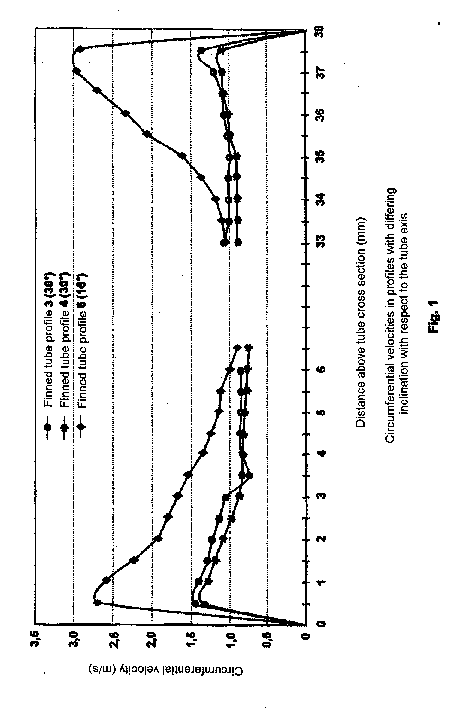
[0026] In the diagram, as shown in FIG. 1: [0027] The upper curve shows: profile 6: 16° pitch [0028] The middle curve shows: profile 3: 30° pitch [0029] The lower curve shows: profile 4: 3 fins with a 30° pitch.

[0030] The curves clearly demonstrate that the higher circumferential velocity of the profile 6 with 4.8 mm high fins is consumed within the fin valleys, whereas the...


PUM

PropertyMeasurementUnit
angleaaaaaaaaaa
inner-wall temperatureaaaaaaaaaa
lengthaaaaaaaaaa

Abstract

In a process for the thermal cracking of hydrocarbons in the presence of steam, the charge mixture is passed through externally heated tubes with helical inner fins, and to make the temperature in the tube wall and over the tube cross section more uniform, as well as to reduce the deposition of pyrolysis coke on the tube inner wall, a swirling flow is generated in the gas mixture and is gradually merged into a core zone with a predominantly axial flow at increasing radial distance from the fins.

Description

CROSS-REFERENCES TO RELATED APPLICATIONS [0001] This application is a continuation of prior filed copending PCT International application no. PCT / EP2003 / 004827, filed May 8, 2003, which designated the United States and on which priority is claimed under 35 U.S.C. §120, the disclosure of which is hereby incorporated by reference, and which claims the priority of German Patent Application, Serial No. 102 33 961.9, filed Jul. 25, 2002, pursuant to 35 U.S.C. 119(a)-(d), the disclosure of which is incorporated herein by reference.BACKGROUND OF THE INVENTION [0002] The present invention relates to a process and a finned tube for the thermal cracking of hydrocarbons in the presence of steam, in which the charge mixture is passed through externally heated tubes with helical inner fins. [0003] Nothing in the following discussion of the state of the art is to be construed as an admission of prior art. [0004] Tube furnaces in which a hydrocarbon / steam mixture is passed through series of indivi...

Claims


Application Information

Patent Timeline
Patent Type & Authority Applications(United States)
IPC IPC(8): C07C4/04C10G9/20F28F1/40
CPCF28F1/40C10G9/20
Inventor WOLPERT, PETERGANSER, BENNOJAKOBI, DIETLINDEKIRCHHEINER, ROLF
Owner SCHMIDT CLEMENS
Why Eureka
Try Eureka