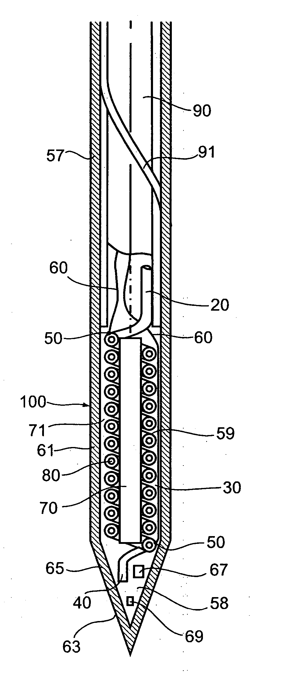
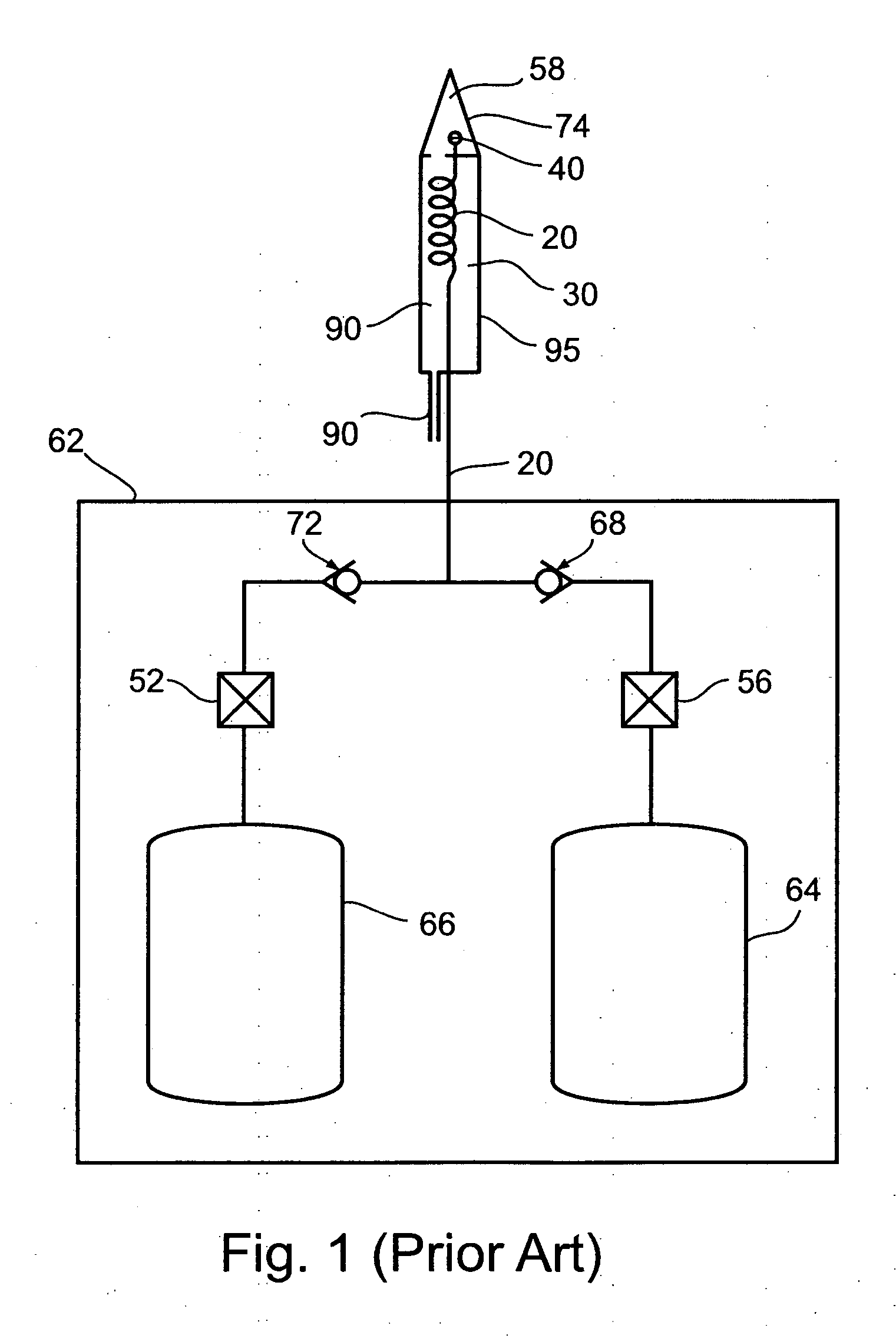
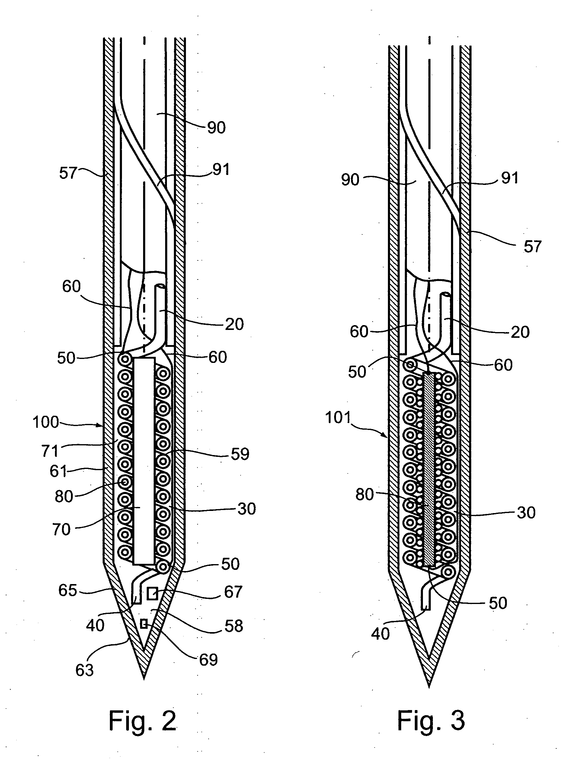
One well-known technical problem in cryoablation is that when a cryoprobe is introduced into an organ or other body part and cooled to cryoablation temperatures, tissues contiguous to the cryoprobe immediately adhere to the probe, sticking to the probe as an ice cube adheres to the hand of an unwary householder using wet fingers to pick up an ice cube from his deep freeze.
Attempts to move or remove a probe by force, while body tissues adhere to the probe, risks tearing or otherwise damaging those tissues.
Adherence of tissues to operating cryoprobes is known to be a source of considerable delays in cryoablation
surgery.
Such delays are particularly problematic under currently preferred
cryosurgery methods, which call for freezing, thawing, and refreezing of tissues, and which may utilize a given probe sequentially in a plurality of positions within an organ, during a process by which a cryoablation locus is shaped and ‘sculpted’ so as to encompass and destroy a
lesion of known three-dimensional shape.
It has been found that cycles of freezing, thawing, and re-freezing are more efficiently destructive of
cell structure than is the process of freezing alone.
A
disadvantage of Ritson's configuration is that it fails to provide rapid and effective and sufficient heating.
A further
disadvantage is that Ritson's configuration requires a high-pressure valve on a high-pressure gas input line, used to switch high-pressure gas from a first gas input line (for conducting high-pressure input gas to the Joule-Thomson orifice, in cooling phase) to a second gas input line, which second line is in non-restricted fluid communication with the
expansion chamber.
Providing the required valve inside the probe and within or near the operating tip is difficult, particularly in view of the extreme
miniaturization of cryoprobes in preferred use today.
Manipulating such a valve during a surgical procedure is difficult also.
Providing the required valve outside the probe, on proximal portions of the gas input lines, creates a latency which causes a lagging
response time when switching between heating phase and cooling phase of operation.
This requirement also creates a barrier to extreme
miniaturization of cryoprobes.
A disadvantage of Glinka's configuration is that it too fails to provide rapid and effective and sufficient heating.
A further disadvantage, of Glinka's configuration is that it also requires an additional gas lumen within the body of the probe, which lumen must, like the gas input lumen common to all Joule-Thomson cryoprobes, be constructed to withstand gas input pressures which may be as high as 4000-6000 psi.
The requirement for this additional high-pressure lumen is problematic in the context of the highly miniaturized cryoprobes in preferred use today.
A disadvantage of Longsworth's configuration is that it too requires an additional gas input lumen extending into a
distal portion of the cryoprobe.
A probe requiring this second gas input lumen is disadvantageous in construction of a highly miniaturized cryoprobes in preferred use today.
Rabin does not, however, disclose a probe operable both to heat and to cool.
Consequently, the probe surface in contact with body tissues cannot itself be an electrical resistance element.
Such a process presents several problems.
Electrical resistance elements, of course, are poor conductors of
electricity, since it is the power expended across the
internal resistance of such heating elements which causes the heating process.
However, poor conductors of
electricity are typically also poor conductors of heat.
Consequently, an electrical resistance element placed in immediate proximity to an external heat-conducting wall of an operating tip of a cryoprobe will inevitably at least partially interfere with the process by which that wall is cooled, during cooling phases of utilization of the cryoprobe.
Thus, a configuration which places an electrical resistance element, and it's necessary electrical insulating layer, within or immediately contiguous to an exterior wall of a probe would enabling heating of that probe, but would also inevitably interfere with the cryoprobe cooling process.
If, however, an electrical resistance element and its necessary electrical
insulation layer are interposed between the
expansion chamber volume and the walls defining that volume, as would be the case if electrical resistance elements are placed within, contiguous to, or
indirect contact with, those walls, then both the resistance elements themselves and their required electrically isolating layer will interfere with
heat transfer between the heat-conductive outer walls and the cold gas contained in the expansion chamber volume, during cooling operation of the probe, since by their nature, electrical insulators and electrical resistance materials are poor conductors of heat.
Thus, electrical resistance elements and electrical insulating
layers in proximity to external walls of the operating tip of a probe (or, alternatively, positioned within those walls) would significantly interfere with the Joule-Thomson cooling process, as described.


