Thermal reservoir for two-pipe hydronic air-conditioning system

a hydronic air conditioner and reservoir technology, applied in indirect heat exchangers, lighting and heating apparatuses, heating types, etc., can solve the problems of two-pipe systems, significant time delay, and increased operating and maintenance costs, so as to reduce time and energy waste, the effect of rapid switching

Inactive Publication Date: 2006-01-31
COMEAUX VERNAL J +1
View PDF8 Cites 95 Cited by
  • Summary
  • Abstract
  • Description
  • Claims
  • Application Information

AI Technical Summary

Benefits of technology

[0009]The general object of the invention disclosed and claimed herein is to provide an improved two-pipe hydronic air-conditioning system, namely to provide one which may be rapidly switched between heating and cooling modes (and the reverse) without unnecessary waste of energy resources. The invention is intended to reduce both the time and energy waste associated with switching said systems between heating and cooling modes (and the reverse). In addition thereto, an object of the invention herein disclosed and claimed is to provide a means for rapidly switching a two-pipe hydronic air-conditioning system from heating to cooling, and the reverse, without the necessity of over-sizing the heating and cooling means of said system. Yet another object of the invention is to be able to affect rapid switching of a two-pipe hydronic air-conditioning system without increasing peak demand for energy utilized by said system.

Problems solved by technology

However, a four-pipe hydronic air-conditioning system, which in essence may be considered substantially “dual” two-pipe systems, has various disadvantages, including but not limited to greater initial cost and additional operating and maintenance expenses.
However a two-pipe system has certain disadvantages, two of which are a significant time delay and energy waste which occurs when a two-pipe hydronic air-conditioning system is switched from heating to cooling mode (or the reverse).
That change of water temperature (by circulation through the system chiller) not only takes a significant length of time to accomplish, but in said process the energy invested in heating the water to about 180 Degrees Fahrenheit is lost, and running of the chiller for said purpose consumes significant amounts of energy to make such temperature reduction.
When switching a two-pipe hydronic air-conditioning system from cooling to heating, a reverse temperature transition must occur producing similar time delay and energy waste.
Moreover, during the significant time when temperature of the water is in transition, the temperature of the air in the building cannot be heated or cooled as desired.
Both this waste of energy and time delay are, of course, highly undesirable.
While switching a two-pipe hydronic air-conditioning system from heating to cooling (or the reverse) might be more rapidly accomplished if an “over-sized” boiler and chiller were used, that solution has disadvantages, including but not necessarily limited to, additional space such equipment may consume, greater cost and maintenance of larger system components and higher peak demand such larger equipment will typically impose on the utility system which power them (which in some cases will result in a higher overall utility rate structure being imposed on the owner / tenant of the building).
Moreover use of over-sized equipment does not solve the energy loss inherent in switching a two-pipe hydronic air-conditioning system from heating to cooling (or the reverse).
Not only is that investment of energy “lost” when hot water in the system is then cooled, cooling it requires consumption of additional energy resources.
It will be recognized that the same problem is presented when switching a two-pipe hydronic system from cooling to heating.
It will be recognized that the aforementioned disadvantages can become acute during seasonal climatic changes, where switching from heating to cooling modes (and the reverse) may sometimes be required on a daily, or even more frequent basis.
Therefore, for instance, during the day, it may take such a long time to switch from heating to cooling (sometimes several hours), that by the time efficient cooling conditions take place, during which air temperature in the building may not be able to be cooled as desired, it is almost time to switch the system back to night-time heating mode.
In this switching back and forth between heating and cooling modes, substantial quantities of energy can be wasted, and air-temperature in the building neither heated or cooled as desired throughout large parts of a 24-hour period of time.

Method used


Image

  • Thermal reservoir for two-pipe hydronic air-conditioning system
  • Thermal reservoir for two-pipe hydronic air-conditioning system
  • Thermal reservoir for two-pipe hydronic air-conditioning system

Examples


Embodiment Construction

[0023]While the present invention will be described with reference to preferred embodiments, it will be understood by those who are skilled in the art that various changes may be made and equivalents may be substituted for elements thereof without departing from the scope of the invention. In addition, many modifications may be made to adapt a particular situation or material to the teachings of the invention without departing from the essential scope thereof. It is therefore intended that the present invention not be limited to the particular embodiments disclosed as the best mode contemplated for carrying out this invention, but that the invention will include all embodiments and legal equivalents thereof which are within the scope of the appended claims.

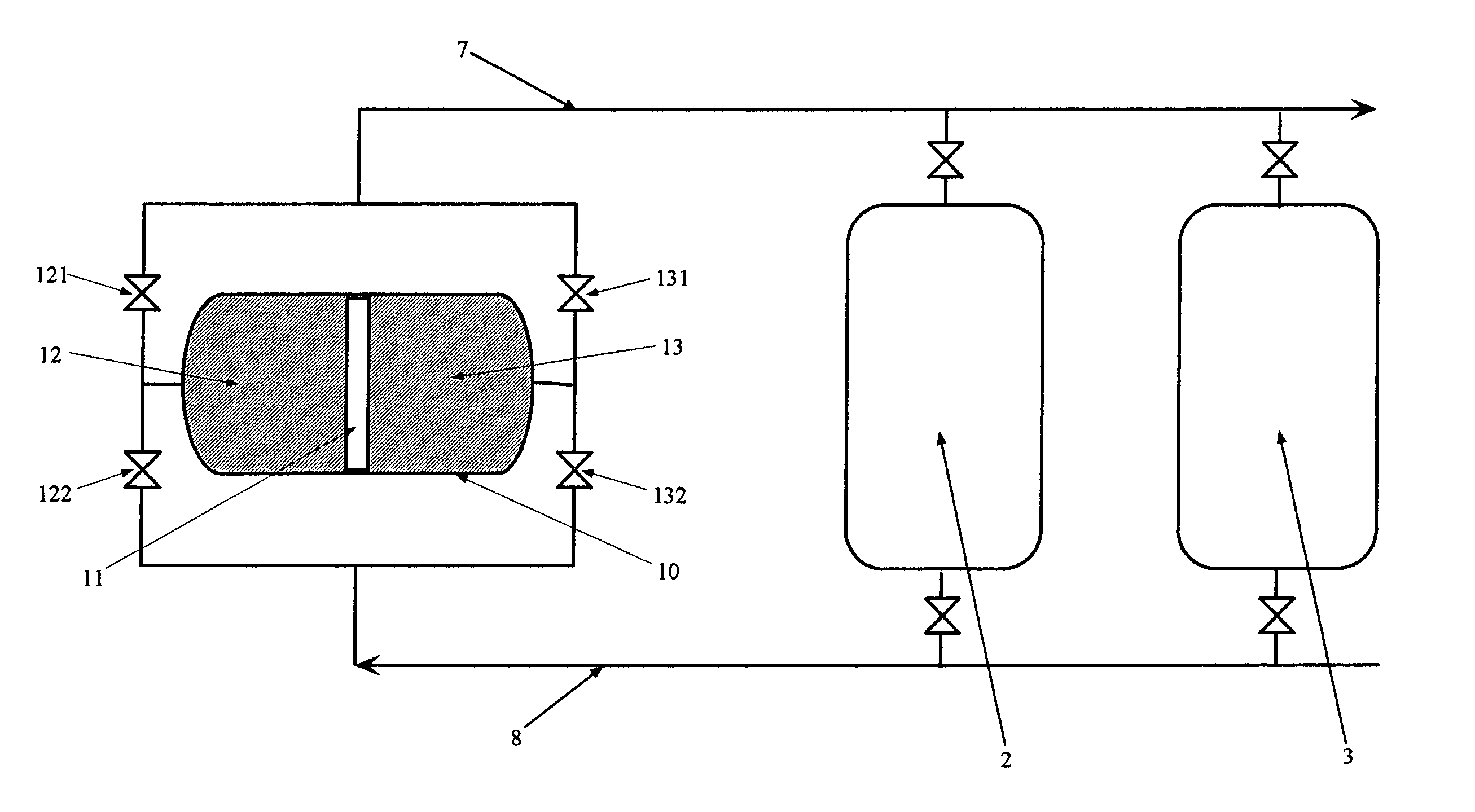
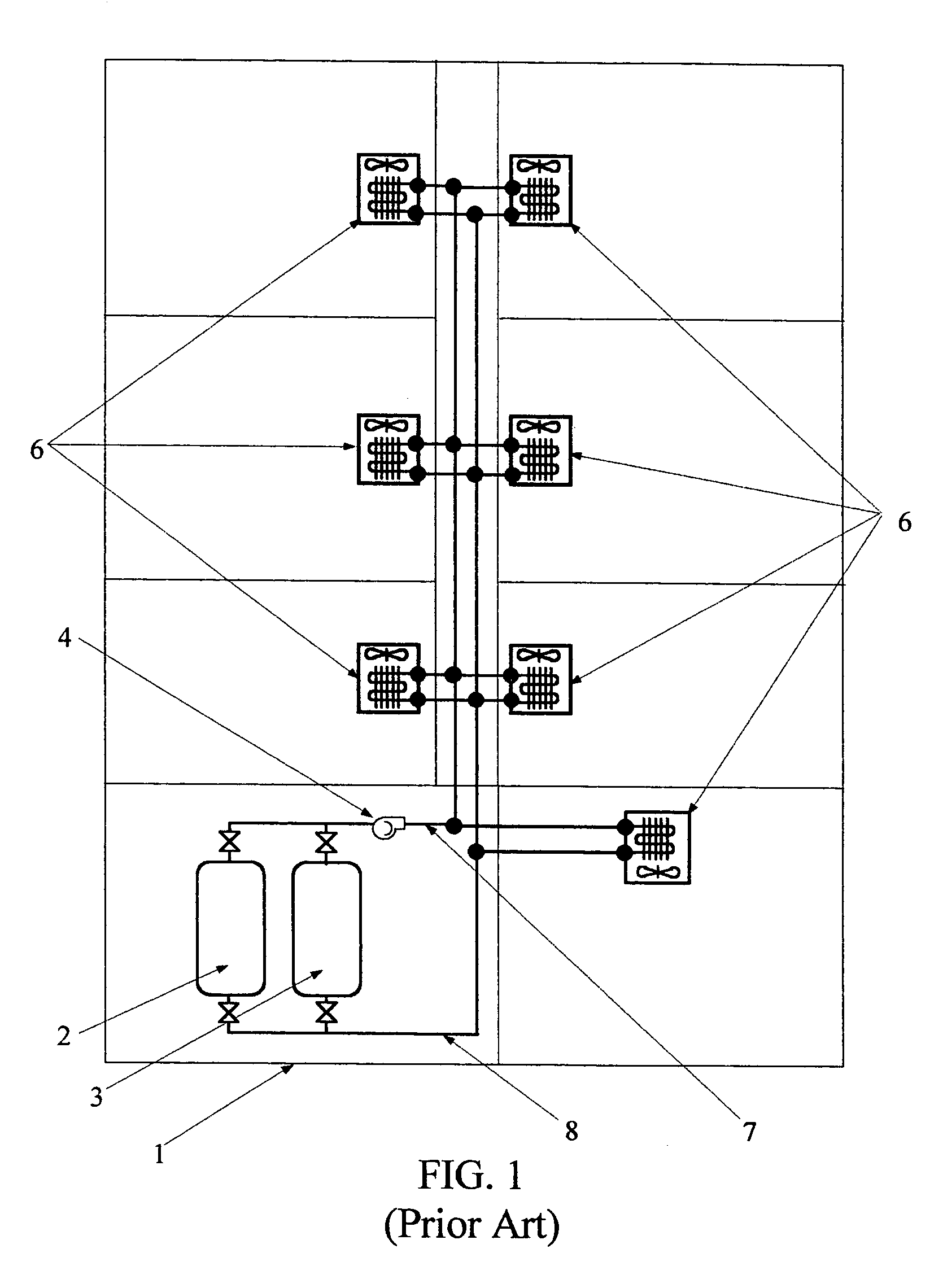
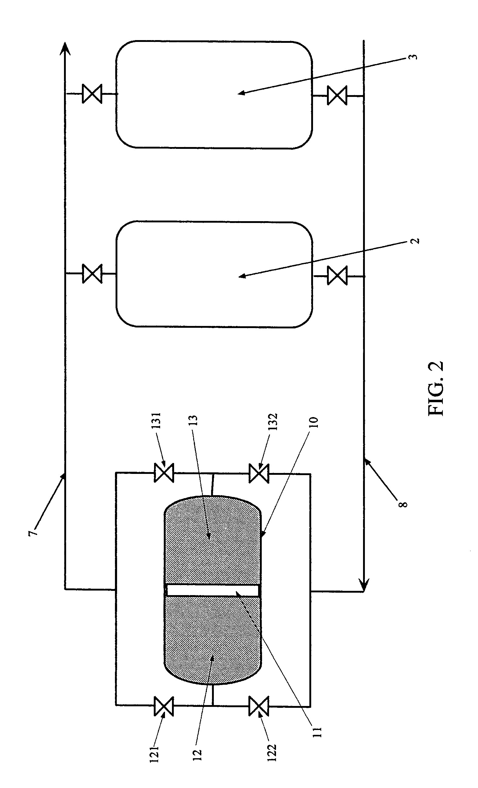
[0024]“Two-pipe” hydronic air-conditioning systems, such as schematically represented in FIG. 1 are known. Such systems are generally used in buildings having multiple zones where individual control of the amount of heating, or al...


PUM


Abstract

A thermal reservoir for a two-pipe hydronic air-conditioning system is disclosed. Said thermal reservoir includes a well-insulated tank for alternatively storing hot and cold water. Said thermal reservoir contains plurality of valves for directing hot water stored therein into the two-pipe hydronic air-conditioning system, thereby causing cold water within the two-pipe hydronic air-conditioning system to be displaced therefrom and into well insulated storage tank. Said process is fully reversible in that cold water displaced from the two-pipe hydronic air-condition system into said thermal reservoir may be subsequently directed from the thermal reservoir and restored to the two-pipe hydronic air-conditioning system and hot water therefrom directed back into storage. Accordingly a two-pipe hydronic air-conditioning system may be switched between heating and cooling modes with rapidity and without waste of the energy content of said hot water and said cold water.

Description

BACKGROUND—FIELD OF THE INVENTION[0001]In the art of heating, cooling and otherwise “conditioning” the air of buildings, “two-pipe” hydronic systems are known. In such systems either hot or cold water, typically from a central location, is circulated about a piping loop. Fluidly attached to said loop, and disposed in zones of the building the air of which is to be conditioned, are a plurality of water-to-air heat exchangers. By regulating the amount of water and / or air which is passed through a particular water-to-air heat exchanger the air of the associated zone may be warmed or alternatively cooled a desired amount. The invention disclosed and claimed herein relates to a thermal reservoir means whereby water stored in said thermal reservoir at one temperature (for instance cold) may be used to reversibly displace water circulating about the piping / heat exchangers at a different temperature (for instance hot) circulating about said piping / heat exchangers, thereby permitting rapid s...

Claims


Application Information

Patent Timeline
Patent Type & Authority Patents(United States)
IPC IPC(8): F24F5/00F25B29/00F24H7/04F24F3/06
CPCF24F3/06F24F5/0017Y02E60/147Y02E60/14
Inventor COMEAUX, VERNAL J.MORGAN, CHRIS D.
Owner COMEAUX VERNAL J
Why Eureka
Try Eureka