Venous heated ablation catheter

a catheter and venous technology, applied in balloon catheters, medical science, surgery, etc., can solve the problems of varicose veins and superficial venous insufficiency, ineffective long-term occlusion maintenance, and high device cost, so as to improve the effectiveness of sclerosant, improve the effect of effectiveness and fluid handling

Inactive Publication Date: 2013-01-31
DRASLER WILLIAM JOSEPH +2
View PDF5 Cites 73 Cited by
  • Summary
  • Abstract
  • Description
  • Claims
  • Application Information

AI Technical Summary

Benefits of technology

[0024]Placement of a heating member in the supply tube that delivers sclerosing fluid to the vessel wall will enhance the effectiveness of the sclerosant. The temperature necessary to provide improved effectiveness is approximately 5-25 degrees Celsius above body temperature; higher temperatures can also be used. At higher temperatures, fluid handling can become more difficult and the pain and neuropathy associated with higher temperature vein ablation would require tumescent anesthesia to be administered.
[0025]In yet another embodiment for the catheter of the present invention, a very low profile delivery catheter is presented that follows over a guidewire that extends from a superficial vein and into a perforator vein and further into the deep venous system. The catheter has two balloons positioned near its distal end and less than 3 cm apart. A distal balloon prevents sclerosant fluid from entering into the deep venous system and can make a seal around the guidewire or at the distal end of the catheter such that the guidewire lumen can be used for removal of effluent sclerosant. The optional proximal balloon can be used to prevent sclerosant fluid from entering the superfic

Problems solved by technology

Superficial veins either below or above the knee can develop incompetent valves with an inability to direct blood from the superficial venous system into the deep system and result in reflux of blood from the deep system into the superficial system.
This reflux of blood can result in varicose veins and superficial venous insufficiency.
Such devices are expensive and are not often effective in maintaining long term occlusion of larger saphenous veins.
With sclerotherapy a liquid sclerosant or a foam sclerosant is injected into the vein to cause trauma to the endothelial lining of the vessel resulting in occlusion of the vein.
Such systems are difficult to control and can result in the sclerosant flowing into the deep venous system potentially causing trauma to this important deep system which is necessary for venous return of blood from the leg to the heart.
The foam sclerosant can also be inconsistent in the size of the bubbles that make up the foam.
It is also not easy for the operator to control the amount of sclerosant that is delivered to the vein and to ensure that the sclerosant does not migrate through the patient's venous system back to his heart, lungs, and potentially bac

Method used


Image

  • Venous heated ablation catheter
  • Venous heated ablation catheter
  • Venous heated ablation catheter

Examples


first embodiment

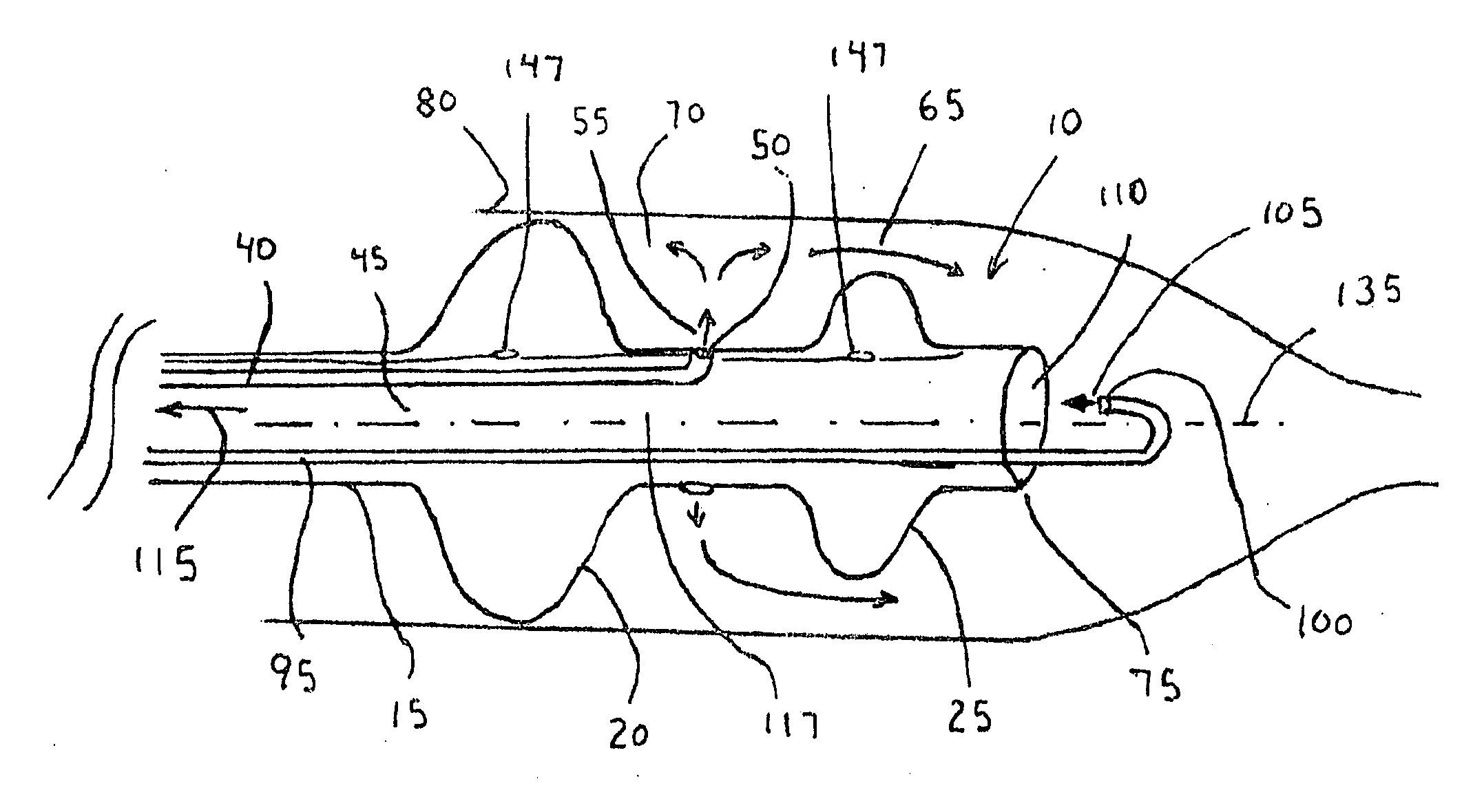
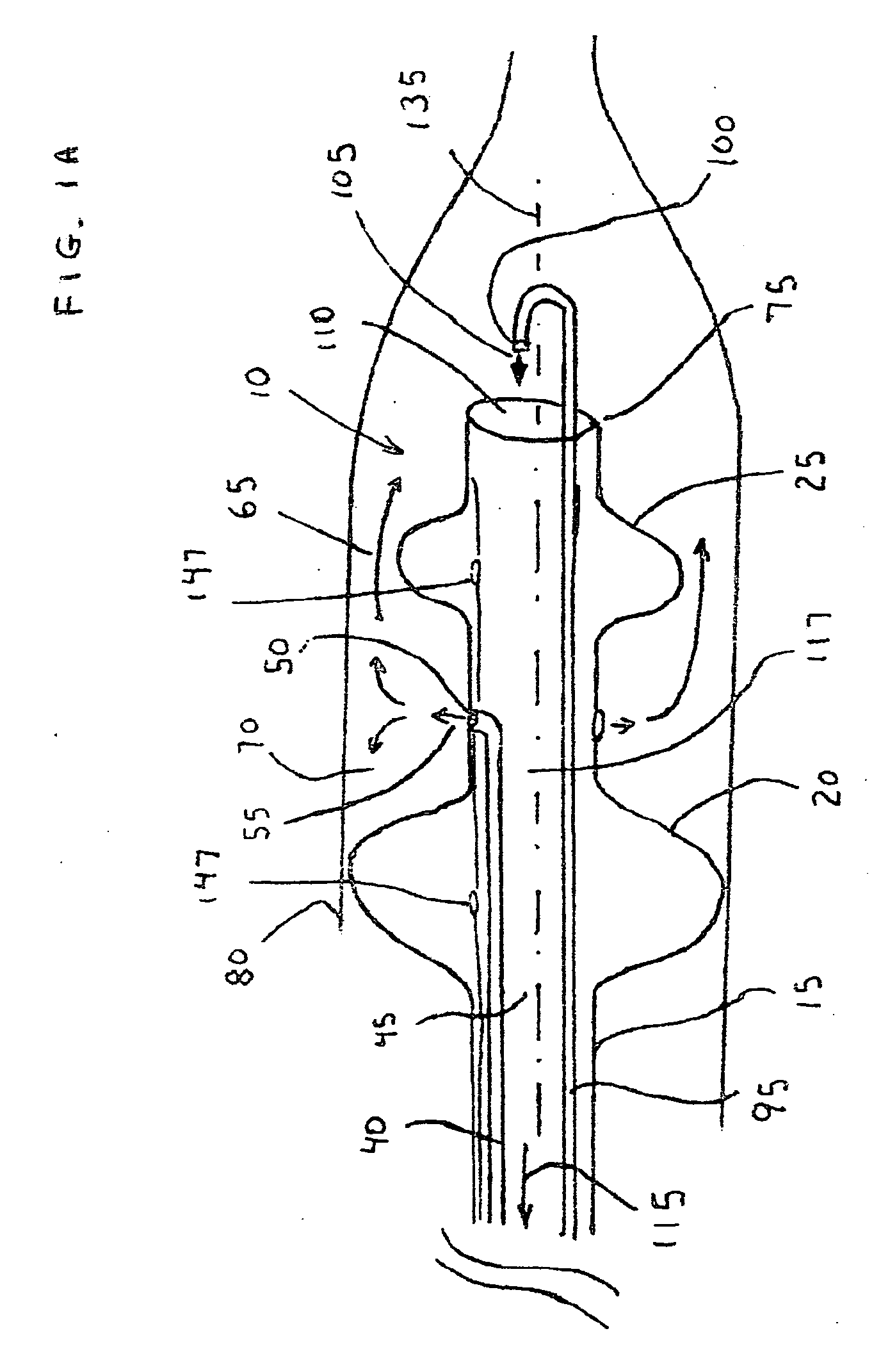
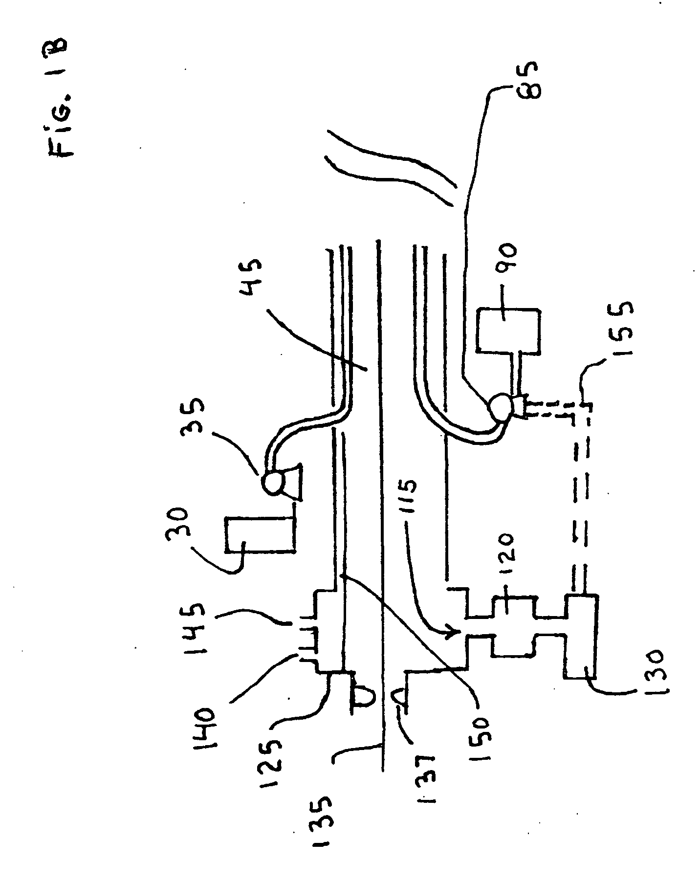
[0080]FIGS. 1A and 1B show the delivery catheter (10). The delivery catheter (10) has a catheter shaft (15) with two balloons located at its distal end (75), a proximal balloon (20) and a distal balloon (25), the distal balloon (25) being somewhat smaller in diameter than the proximal balloon (20). The proximal balloon (20) makes contact with the vein to be treated and forms a seal along the perimeter of the balloon. A sclerosant solution is delivered from a first reservoir (30) by a first pump (35) to a side tube (40) located in the shaft lumen (45) to a side orifice (50) located between the balloons and directed outwards to form a side jet (55). The sclerosant solution can be formed from a sclerosing agent such as STS, POL, sodium morrhuate, ethanolamine oleate, glycerin, hypertonic saline, mixtures with alcohol or dextrose, iodine compounds, or other known sclerosing agents mixed with saline and having a CO2 gas or other soluble gas dissolved in the solution. Upon the side jet (5...

third embodiment

[0091]In a third embodiment the sclerosing medium can be a heated saline solution, heated sterile water, heated mixture, or heated sclerosing solution that causes the wall of the vein to become necrotic upon or soon after its contact. The heated saline or fluid can be heated via any means used in the medical device industry for heating a fluid to a temperature greater than 45 degrees Celsius such as with an electrical resistance heater. The heated fluid could be warmed to a preferred temperature that ranges from 45-55 degrees C. for improved ablative effectiveness; temperatures higher than this can also be used with increased effectiveness but with the potential for neurological pain. The distal jet (105) can also have heated saline or also it could be saline at normal body temperature to help return the vein to an equilibrium state that is closer in temperature to a normal body temperature. The heated fluid agent can effectively ablate a large superficial vein and can also make dir...


PUM


Abstract

A catheter for delivery of sclerosant to a tubular member or vein of the body to cause ablation. The catheter has one or more balloons located near the distal end to enhance effectiveness of the sclerosant and prevent its delivery to the deep venous system. The catheter has an orifice located near the distal end of the catheter to direct the sclerosant into the vessel and one or more effluent openings to provide for removal of the sclerosant fluid. A heating member such as an electrical resistance element, a Laser probe, or an RF electrode located within the catheter lumen or on the outside of the catheter shaft heats the sclerosant fluid to improve its ablation effectiveness.

Description

CROSS REFERENCE TO RELATED APPLICATIONS[0001]This nonprovisional patent application makes reference to and includes information found in the provisional patent applications No. 61 / 458,394 entitled “Venous Ablation Catheter” filed 23 Nov. 2010 by William J. Drasler, “Venous Perforator Ablation Catheter” filed 22 Aug. 2011 by William J. Drasler, and No. 61 / 575,530 entitled “Venous Heated Ablation Catheter” filed 23 Aug. 2011 by William J. Drasler, Kevin Nickels, and Edward Black.FIELD OF THE INVENTION[0002]This invention relates to an interventional device that is placed into a lumen of the body such as a vein to ablate or occlude the venous lumen.BACKGROUND OF THE INVENTION[0003]Superficial veins either below or above the knee can develop incompetent valves with an inability to direct blood from the superficial venous system into the deep system and result in reflux of blood from the deep system into the superficial system. Such reflux can occur at the junction of a superficial vein ...

Claims


Application Information

Patent Timeline
IPC IPC(8): A61M25/10
CPCA61B2018/046A61B2018/044A61B2018/048A61B18/04A61M25/1011A61B2018/00577A61B18/1492A61B18/22A61B2017/22082A61B2018/00285A61M2025/1052A61B17/320725A61B17/12186A61B17/12136A61B17/12045A61M25/10
Inventor DRASLER, WILLIAM JOSEPHNICKELS, KEVIN LEROYBLACK, EDWARD JAMES
Owner DRASLER WILLIAM JOSEPH
Why Eureka
Try Eureka