Elongated led lighting fixture

a technology of led lighting fixtures and led lamps, which is applied in the direction of lighting and heating apparatus, furniture, domestic cooling apparatus, etc., can solve the problems of high material and component cost, difficult and time-consuming assembly, uneven light distribution and brightness, etc., and achieve the effect of increasing the lighting performance of the fixture and widening the illumination rang

Active Publication Date: 2008-02-14
ELECTRALED
View PDF54 Cites 184 Cited by
  • Summary
  • Abstract
  • Description
  • Claims
  • Application Information

AI Technical Summary

Benefits of technology

[0006] The present invention is directed to a lighting fixture having two groups or arrays of LED modules that are angularly positioned to each other to produce a broad range of illumination. The fixture includes an elongated housing with angled support members, a group of LEDs mounted to each support member, opposed end walls, and a cover that couples to the housing and extends between the end walls. The housing further includes a wing extending from a lowermost region of each support member wherein the wing blocks glare from the LEDs during operation of the fixture. Each LED is part of a module that is connected to an outer surface of one of the support members by a pair of elongated fasteners. An interconnection bus is energized by an internal power supply and is positioned within a channel adjacent an inner surface of each support member by the fasteners. Current flows from the interconnection bus through the fasteners to the module to illuminate the LED thereon. Preferably, each group of LEDs includes a number of modules affixed to a support member. Because the support members are angularly oriented, the two groups of LEDs are similarly angled. The angled orientation of the two LED groups increase the light distribution angle of the fixture, thereby increasing the lighting performance of the fixture.
[0008] Due to the angled mounting of the two groups of LED modules, the fixture's light emitting angle is significantly greater than conventional fixtures having LEDs arrayed in a single plane. In addition to having a broader light emitting angle and light pattern, the fixture has a longer service life, is more durable and operates more efficiently, both electrically and thermally, than conventional light fixtures including neon, fluorescent, cold cathode, halogen, high-pressure sodium, metal halide, and incandescent. The LED modules increase the utility of the fixture for cold temperature applications, since cold temperatures extend the operating life of the LEDs. Along these lines, the fixture is especially well-suited for use in coolers and freezers, including open-top versions and those with doors, and cold food lockers. The fixture can also be used as original equipment or retrofit in connection with product displays and racks, backlighting, and indirect or ambient applications, regardless of the temperature environment. For example, the fixture can be configured for indirect architectural use, such as a cove fixture in retail stores.

Problems solved by technology

While such fixtures provide some beneficial features, they nevertheless suffer from a number of limitations, including but not limited to, uneven light distribution and brightness, high material and component costs, difficult and time-consuming assembly, and cumbersome housing configurations that hamper installation and thus prevent custom applications.
Because the LEDs 44 are linearly arranged in a single plane, the tube 20 produces a limited range of light that is uneven and susceptible to undesirable “hot spots.” This poor lighting performance renders the tube 20 commercially unfeasible.

Method used


Image

  • Elongated led lighting fixture
  • Elongated led lighting fixture
  • Elongated led lighting fixture

Examples


Embodiment Construction

[0023] While this invention is susceptible of embodiments in many different forms, there are shown in the drawings and will herein be described in detail preferred embodiments of the invention with the understanding that the present disclosure is to be considered as an exemplification of the principles of the invention and is not intended to limit the broad aspect of the invention to the embodiments illustrated.

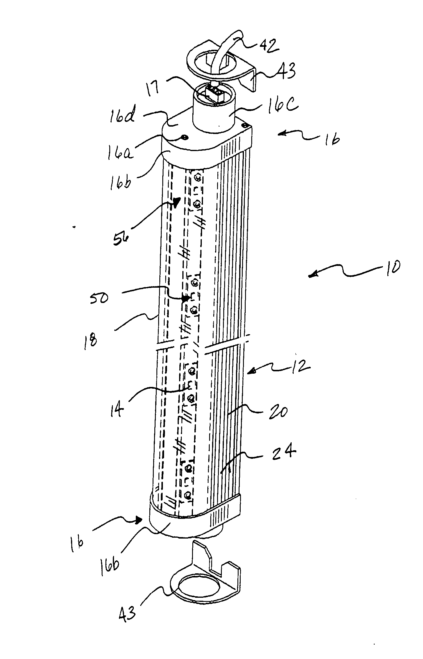
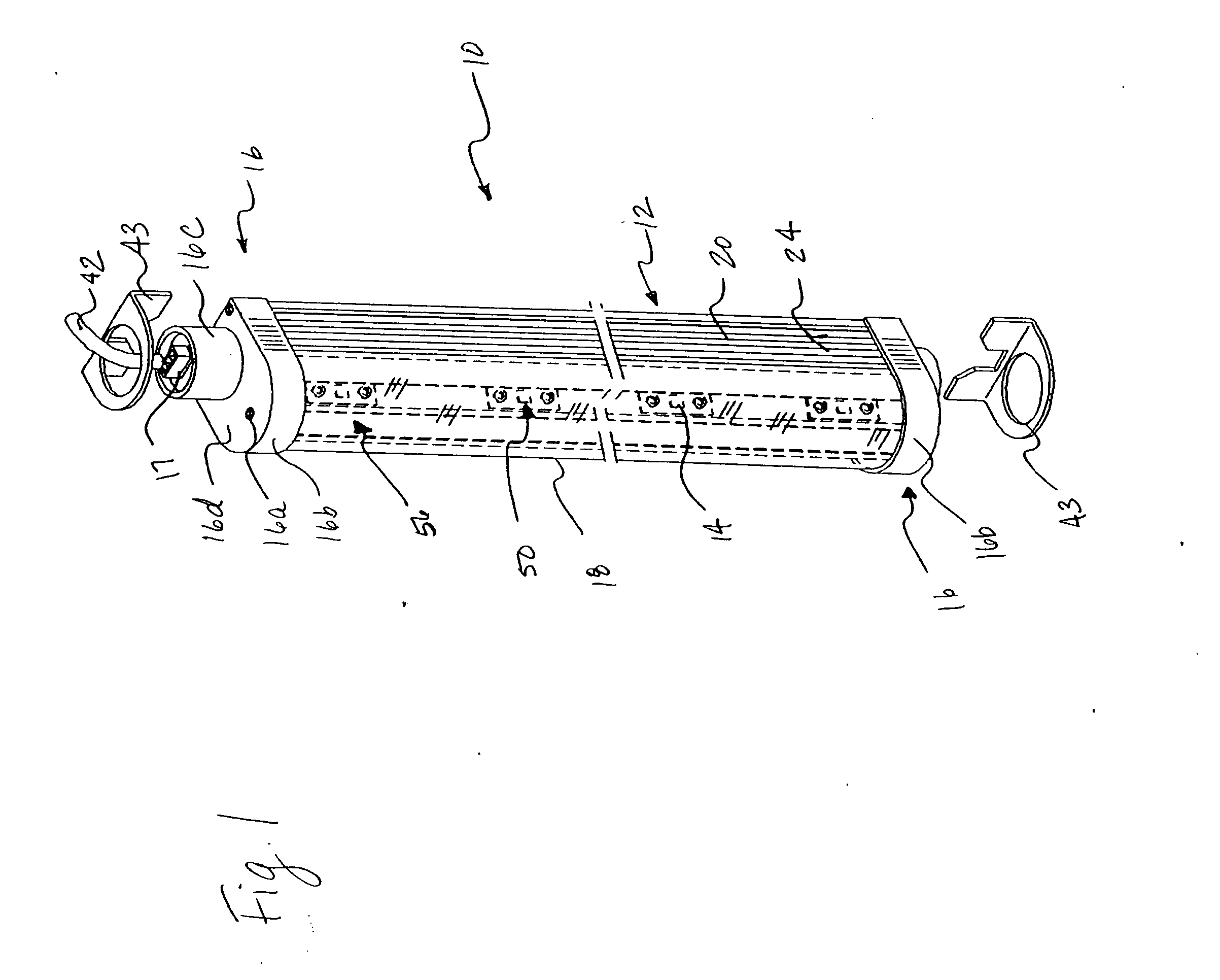
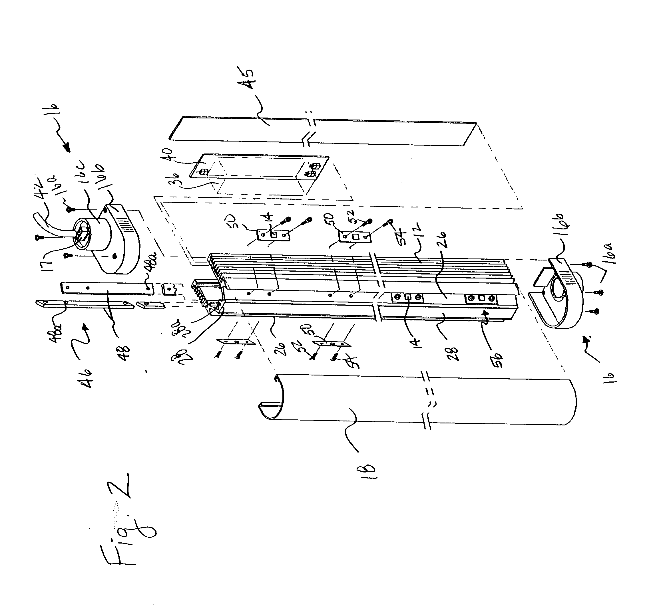
[0024]FIGS. 1-7 show an elongated lighting fixture 10 of the present invention. The fixture 10 comprises an elongated extrusion or housing 12, at least two light emitting diodes (LEDs) 14 angularly mounted within the housing 12, opposed end caps 16, and a generally transparent cover 18 that couples to the housing 12 and extends between the end plates 16. As explained in greater detail below, the fixture 10 includes two groups of uniquely positioned LEDs 14 that improve the operating performance of the fixture 10 while lowering the material and assembly costs of the fixture 1...


PUM


Abstract

The invention provides an elongated lighting fixture with multiple light emitting diodes (LEDs) arrayed in two groups that are angled to each other. The fixture provides an extremely broad light emitting angle and includes an elongated housing having a pair of side walls with at least one fin to dissipate heat. Each side wall has a support member extending upward at angle from the side wall, wherein the side walls terminate at a central wall. A generally transparent cover is connected to the housing and extends between opposed ends of the housing. A first elongated fastener and a second elongated fastener are utilized to mount a first group of LEDs and a second group of LEDs to the first support member and the second support member, respectively. First and second interconnection board assemblies are affixed to respective support members beneath the group of LEDs by the first and second fasteners. When the first and second interconnection board assemblies are energized by an internal power source, current travels from each interconnection assembly through the fasteners to each group of LEDs for illumination.

Description

CROSS-REFERENCE TO RELATED APPLICATIONS [0001] This Application claims the benefit of U.S. Provisional Application No. 60 / 187,913 which was filed on Jun. 30, 2006.FEDERALLY SPONSORED RESEARCH OR DEVELOPMENT [0002] Not applicable. TECHNICAL FIELD [0003] The invention relates to an elongated lighting fixture with multiple light emitting diodes (LEDs) arrayed in two groups that are angled to each other. The fixture includes an elongated housing with two angled support members to which an array of LED modules are mounted, an electrical interconnection board affixed to an inner surface of each support member, a curvilinear cover, and an internal power supply. The fixture may also include bypass circuitry to prevent multiple LED modules from not illuminating, and remote operations capability. BACKGROUND OF THE INVENTION [0004] There currently exists a number of lighting fixtures utilizing LEDs as the light source. While such fixtures provide some beneficial features, they nevertheless suf...

Claims


Application Information

Patent Timeline
Patent Type & Authority Applications(United States)
IPC IPC(8): F21V33/00F21S4/00F25D27/00
CPCF21S4/008F21V15/013F21V15/015F21V29/004F21V29/76F21Y2101/02F21Y2103/003F25D27/00F21V29/71F21W2131/305F21S4/28F21Y2103/10F21Y2115/10F21V29/83
Inventor THOMAS, JAMESLYND, DAVIDGATESMAN, GARYMOSIER, JIMWARNER, BRYAN T.
Owner ELECTRALED
Why Eureka
Try Eureka