Wind flow body for a structure and method of use thereof

a technology of flow body and wind flow, which is applied in the direction of building components, climate change adaptation, roof covering, etc., can solve the problems of destabilizing the fit of the roof, and affecting the stability of the structur

a technology of flow body and wind flow, which is applied in the direction of building components, climate change adaptation, roof covering, etc., can solve the problems of destabilizing the fit of the roof, and affecting the stability of the structur

US20080083171A1Inactive Publication Date: 2008-04-10GRAF CHRISTOPH

Image

  • Wind flow body for a structure and method of use thereof
  • Wind flow body for a structure and method of use thereof
  • Wind flow body for a structure and method of use thereof

Examples


Embodiment Construction

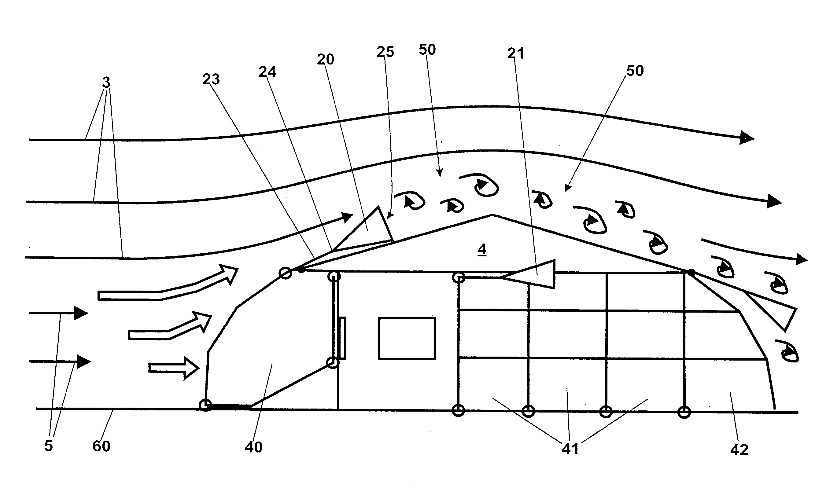
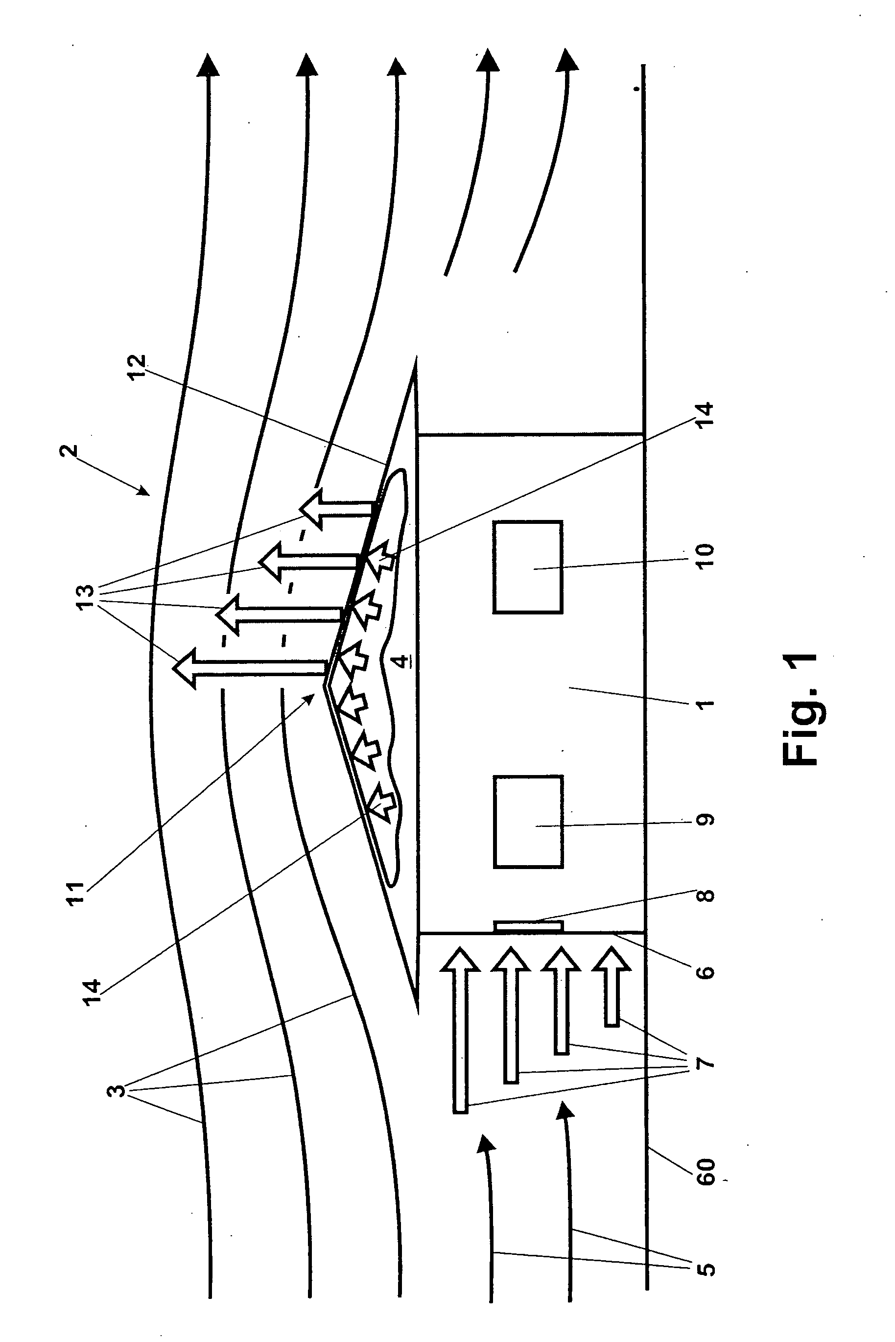
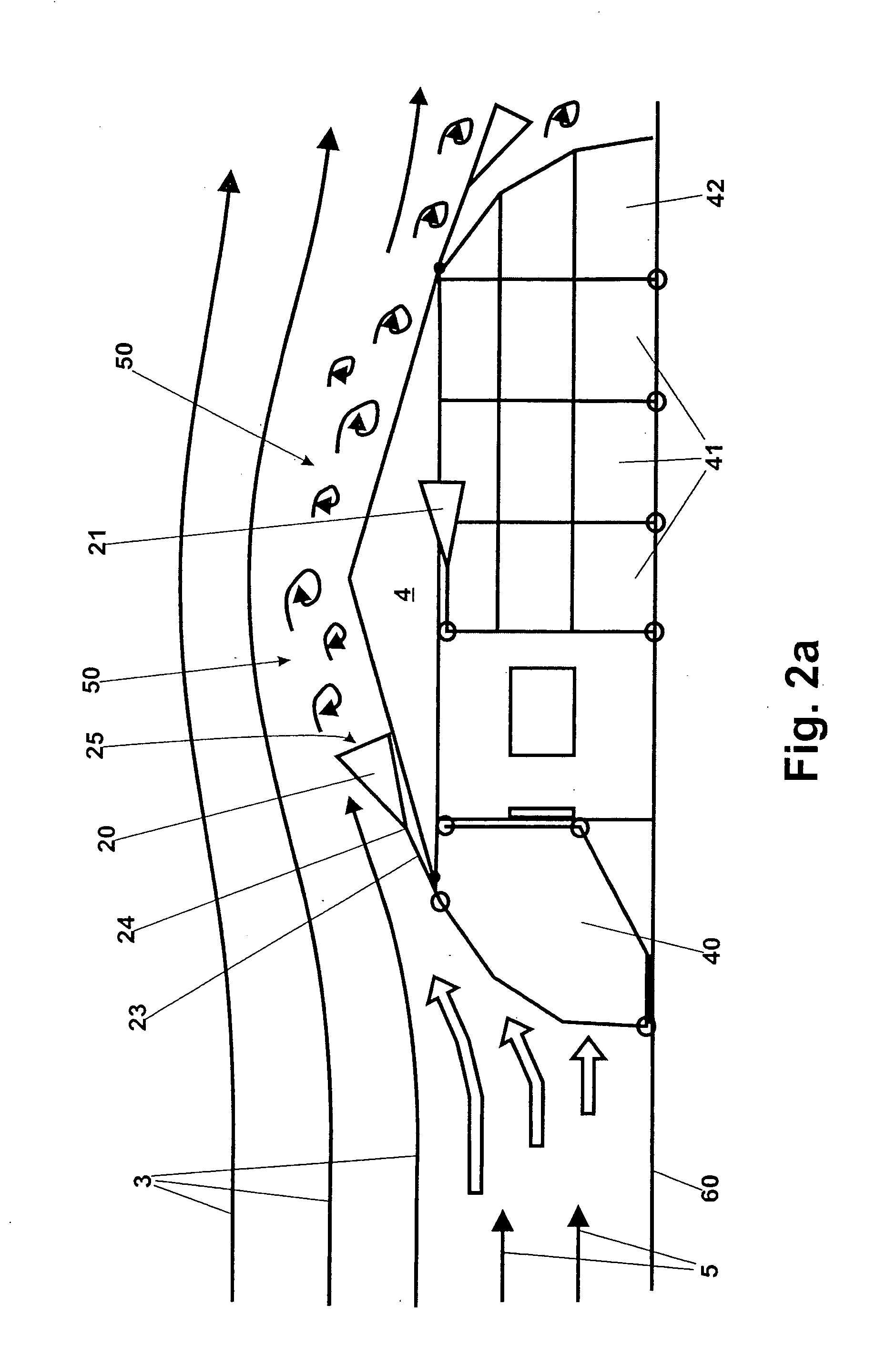
[0025]FIG. 1 shows a structure, here a home 1, exposed to a heavy wind 2 or storm, such as, for example, a hurricane. Flow paths 3 of the wind 2 are illustrated, which essentially extend across the roof 4 of the home 1, while flow paths 5 of the wind 2 are directed against a wall 6.

[0026]The wind force acting on the wall 6 due to the wind portion corresponding to the flow paths 5 is illustrated by the force vectors 7. Corresponding to the boundary layer, which allows only low wind speeds in the immediately vicinity of the ground level, the force vectors 7 increase with increasing distance to the support 60, until they finally correspond to the force of the freely blowing storm, for example at the height of the roof 4.

[0027]Windows 8, 9, 10 are further illustrated, whereby in the instant example, the window 8 is directly subjected to the dynamic pressure of the wind 2 represented by the vectors 7.

[0028]The storm, corresponding to the flow paths 3, blowing across the roof creates an u...


PUM


Abstract

The present invention provides wind flow bodies for use with a structure for decreasing the carrier wing effect on the structure by the formation of turbulence or reducing the dynamic pressure by deflecting the wind flow. The invention further provides a method for securing the composition of a structure against the onslaught of heavy winds, whereby zones, which are suitable for the formation of a critical carrier wing effect during heavy wind flow are identified on the structure, and the position of a wind flow body for generating turbulence for dampening the carrier wing effect, is then determined. Further zones are identified which are suitable for the formation of the dynamic pressure, and the operating position of a wind flow body is then determined for deflecting the corresponding wind flow for reducing the dynamic pressure.

Description

FIELD OF THE INVENTION[0001]The present invention generally pertains to a wind flow body for use with a structure and more particularly to a wind flow body positionable relative to a structure for changing the wind flow forces affecting the structure and method of use thereof.BACKGROUND OF THE INVENTION[0002]Heavy winds, such as storm winds, hurricanes or typhoons (which are named differently, depending on the region, but which can always reach considerable strength) routinely lead to considerable damages on structures of all types, particularly homes. It is thereby unpredictable, whether a structure will be affected only slightly or heavily. Storm damages extend from possibly damaging individual windows or the loss of a few roof tiles or purlins to the complete destruction of the structure or the home. Likewise, a rather mild storm can cause larger damages or a very heavy storm can cause comparatively small damages.[0003]Simpler constructions, such as wooden homes or even transport...

Claims


Application Information

Patent Timeline
10 Apr 2008
Publication
US20080083171A1
IPC
E04D1/30
CPC
E04H9/14; E04D13/00; Y02A50/00
Inventors
GRAF, CHRISTOPH