Developing Device and Image Forming Apparatus Using the Same

a technology of developing device and image forming apparatus, which is applied in the direction of electrographic process apparatus, instruments, optics, etc., can solve the problems of reducing toner charging property, frequent generation of poorly charged toner particles, and deterioration of the resettability of toner particles, so as to prevent the accumulation of excess toner particles, prevent failure, and prevent the effect of occurrence of failur

Inactive Publication Date: 2008-11-06
SEIKO EPSON CORP
View PDF3 Cites 18 Cited by
  • Summary
  • Abstract
  • Description
  • Claims
  • Application Information

AI Technical Summary

Benefits of technology

[0016]According to the present invention, it is possible to realize a developing device and an image forming apparatus capable of preventing deterioration of the resettability of the toner particles to prevent excess charge of the toner particles, thereby preventing occurrence of failure caused by an decrease in toner flying property between the developing roller and photoconductor or a change in development characteristics.
[0017]Further, according to the present invention, it is possible to realize a developing device and an image forming apparatus capable of preventing poor charging of the toner particles to prevent overlapping of the toner particles which incurs waste of the toner.

Problems solved by technology

However, a new problem has arisen in the development roller having the regular groove shape as disclosed in JP-A-2000-56558.
That is, the toner conveyed to the surface of a developing roller clogs in the groove portion and the toner entering the groove cannot be reset.
When such residual toner is ground by a regulation blade again and again, toner charge becomes excessively high, decreasing toner flying property between the developing roller and photoconductor or changing development characteristics, which causes failure.
Another disadvantage is that the developing roller having the regular groove shape as disclosed in JP-A-2000-56558 has a reduced toner charging property as compared to a developing roller having an irregular surface configuration.
Although it is ideal for all the toner particles to be subjected to uniform friction for charging, the developing roller having a regular surface configuration has a reduced toner charging property as compared to the developing roller having an irregular surface configuration, resulting in frequent generation of poorly charged toner particles.
The existence of the poorly charged toner particles (in this case, positively charged toner particles, not negatively charged toner particles) causes overlapping of the toner particles, incurring waste of the toner.

Method used


Image

  • Developing Device and Image Forming Apparatus Using the Same
  • Developing Device and Image Forming Apparatus Using the Same
  • Developing Device and Image Forming Apparatus Using the Same

Examples


example 1

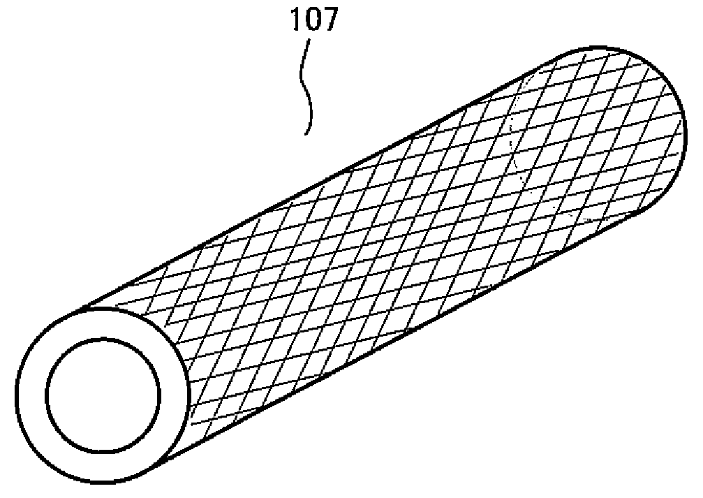
[0072]As the developing roller 107 for the developing device 100 according to the present embodiment, a developing roller having a groove portion in which the leading end side cutting angle θ1=30° and trailing end side cutting angle θ2=60° was produced. Further, as a developing roller for the developing device 100 according to a comparative example, a developing roller having a groove portion in which the leading end side cutting angle θ1=45° and trailing end side cutting angle θ2=45° was produced. The groove pitch of both the developing rollers was set to 80 μm.

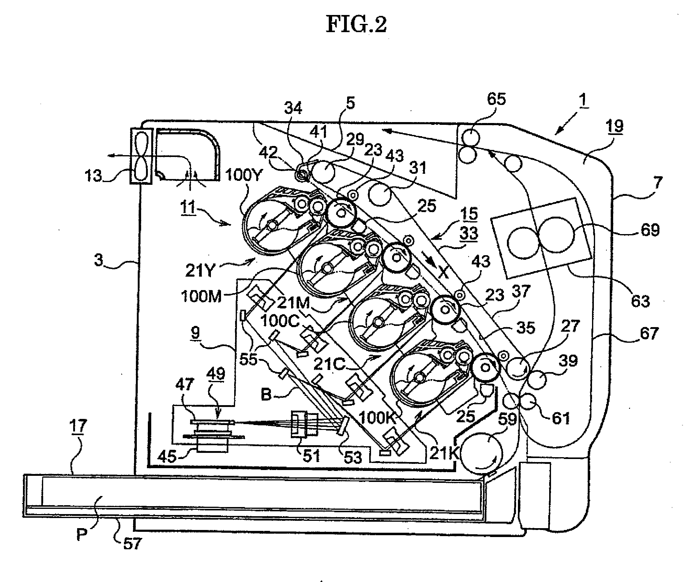
[0073]The developing device 100 according to the present embodiment and the developing device 100 according to the comparative example respectively incorporating the above developing rollers were mounted in the image forming apparatus 1 shown in FIG. 2 to perform a print test under the conditions described below

(Driving Speed)

[0074]Photoconductor: 200 mm / sec[0075]Developing roller: 300 mm / sec

[0076](with rotation at the nip p...

example 2

[0103]As the developing roller 107 for the developing device 100 according to the present embodiment, a developing roller having a groove portion in which the leading end side cutting angle θ1=60° and trailing end side cutting angle θ2=30° was produced. Further, as a developing roller for the developing device 100 according to a comparative example, a developing roller having a groove portion in which the leading end side cutting angle θ1=45° and trailing end side cutting angle θ2=45° was produced. The groove pitch of both the developing rollers was set to 80 μm.

[0104]The developing device 100 according to the present embodiment and the developing device 100 according to the comparative example respectively incorporating the above developing rollers were mounted in the image forming apparatus 1 shown in FIG. 2 to perform a print test under the conditions described below.

(Driving Speed)

[0105]Photoconductor: 200 mm / sec[0106]Developing roller: 300 mm / sec

[0107](with rotation at the nip ...


PUM


Abstract

To provide a developing device capable of preventing excess charge of the toner particles so as to prevent occurrence of failure caused by an decrease in toner flying property between the developing roller and photoconductor or a change in development characteristics, a developing device according to the present invention develops non-magnetic mono component toner using a developing roller having on its surface a plurality of groove portions each of which includes: a leading end side cut portion formed on the leading end side of the developing roller in the rotational direction thereof and having a leading end side cut angle θ1; and a trailing end side cut portion formed on the trailing end side of the developing roller in the rotational direction thereof and having a trailing end side cut angle θ2 and in which a relationship θ1<θ2 is satisfied.

Description

CROSS REFERENCE TO RELATED APPLICATIONS[0001]This application is based upon and claims the benefit of priority from prior Japanese Patent Applications No. 2006-330236, filed Dec. 7, 2006 and No. 2006-330237, filed Dec. 7, 2006, the entire contents of which are incorporated herein by reference.BACKGROUND OF THE INVENTION[0002]1. Field of the Invention[0003]The present invention relates to a developing device performing development using non-magnetic mono component toner through toner jumping phenomenon and an image forming apparatus using the developing device.[0004]2. Description of the Related Art[0005]In an image forming apparatus using non-magnetic mono component toner as disclosed in JP-A-2001-66876, an electrical charge is applied to toner on a developing roller (sleeve) by frictional electrification. In order to effectively generate frictional electrification, that is, in order for the toner to be satisfactorily subjected to friction with the developing roller, blast treatment...

Claims


Application Information

Patent Timeline
Patent Type & Authority Applications(United States)
IPC IPC(8): G03G15/08
CPCG03G15/0818G03G2215/0619G03G2215/0634
Inventor TOYAMA, HIROSHIIKUMA, KEN
Owner SEIKO EPSON CORP
Why Eureka
Try Eureka