Retraction Apparatus And Method Of Use

a tissue retractor and tissue technology, applied in the field of retractors and methods, can solve the problems of significant space difference between blades, injury and trauma to the patient's body, and increase the difficulty of retraction, so as to minimize tissue and blood encroachment and optimize the access to the surgical site

Active Publication Date: 2009-03-12
XTANT MEDICAL HLDG INC
View PDF61 Cites 42 Cited by
  • Summary
  • Abstract
  • Description
  • Claims
  • Application Information

AI Technical Summary

Benefits of technology

[0007]In accordance with one aspect of the present invention, access retraction apparatus and methods are disclosed that provide optimized access to a surgical site through an incision during a surgical procedure. To this end, the apparatus and methods utilize tissue engagement members, such as in the form of retractor blades. The retractor blades are operable to pull tissue about the incision apart while substantially minimizing tissue and blood encroachment into the surgical site during surgical procedures. The preferred retractor includes a frame or body having a retraction opening in which the retractor blades are operable to provide optimized access to the surgical site by keeping tissue encroachment beyond the retracted blades to a minimum. Sets of opposing blades are provided, including a set having a narrow width and a set having a comparatively wide width. Operating mechanisms for the blades are configured to allow for sequential retraction of the sets of blades which, in turn, allow for gaps between the blades to be minimized in size.
[0008]In one form, the narrow width blade set is initially retracted in a first direction. The wide width blade set can then be inserted into the enlarged opening and retracted to further enlarge the opening in a second direction transverse, and preferably perpendicular, to the first direction in order to retract the tissue to form an oblong opening surrounded by the blades. The use of two different blade widths and the sequential use of those blades permits the gaps between adjacent blades to be minimized to reduce encroachment of tissue through the gaps.
[0010]Each of the blades is preferably removably attached to a slider mechanism to allow for shifting of the blades to different positions. The set of narrower blades, which retract first, preferably have a ratcheting slider mechanism that provides retraction over small increments. This provides numerous closely spaced, predetermined retraction positions for the narrow blades. Subsequently, the wide blades are retracted. The wide blades can be selected from a plurality of different widths. In one aspect, the wide blades have only two positions, retracted and extended. In another aspect, the wide blades also use a ratcheting slider mechanism that provides retraction over small increments. The width of the wide blades used is limited by how far the narrower blades were retracted in the first or initial stage of retraction. Substantially matching the width of the wide blades to the distance traveled by the narrow blades during the first retraction stage ensures that minimal space will be available between the blades for tissue encroachment. In addition to allowing for different sizes of blades to be interchanged, and in particular for the blades of the wide blade set used with the retractor, the detachable connections also enable the blades and slider mechanisms to more easily be cleaned and sanitized.
[0012]In one form, the retractor opening is generally oblong, i.e., having a length that is substantially greater than its width. However, in another form the retractor opening has a length that is close to or about the same as its width. The opening can have a variety of shapes, such as generally circular, ovoid, rectangular, or square. For generally rectangular or square openings, the inner corners are slightly curved so that radii thereof are kept to a minimum to provide for increased area of the opening, and thus increased access space for the surgeon. Depending upon the shape and size of the retractor opening, the retractor can accommodate four blades of relatively equal width or blades having multiple widths. Increasing the area of the opening can provide the surgeon with flexibility such that different patients and procedures can more easily be accommodated.
[0013]In yet another form, the frame or body of the retractor may have positions or sections that are adjustable relative to each other, such as by pivoting. In this regard, the retractor frame has at least one articulating section. This section may be hingedly or pivotally attached or otherwise moveably attached to the remainder of the frame and may be releasably fixable relative to the remainder of the frame. A retractor with such articulation capabilities can move from a relatively planar profile to a profile that more closely corresponds to the contours of the patient's body, to allow for ease of insertion into the underlying incision. With more precise positioning of the retractor relative to the tissue surrounding the incision, the retractor can provide better access to the surgical site and reduce the stress and trauma to the patient, and more particularly, the surgical site and the tissue adjacent thereto. Such an articulating section may include a set of pivot connections on the retractor frame. In one embodiment, the pivot connections are hinges located on either side of the retractor frame. In another embodiment, two or more articulating sections may be provided.

Problems solved by technology

While incisions are required during surgical procedures to gain access to the surgical site, such incisions can cause damage, injury, and trauma to the patient's body.
A significant problem with retractors currently used during surgical procedures, is that after the blades are moved from the unretracted position to the retracted position, the blades are spaced significantly apart.
The gaps can become increasingly problematic throughout the procedure.

Method used


Image

  • Retraction Apparatus And Method Of Use
  • Retraction Apparatus And Method Of Use
  • Retraction Apparatus And Method Of Use

Examples


first embodiment

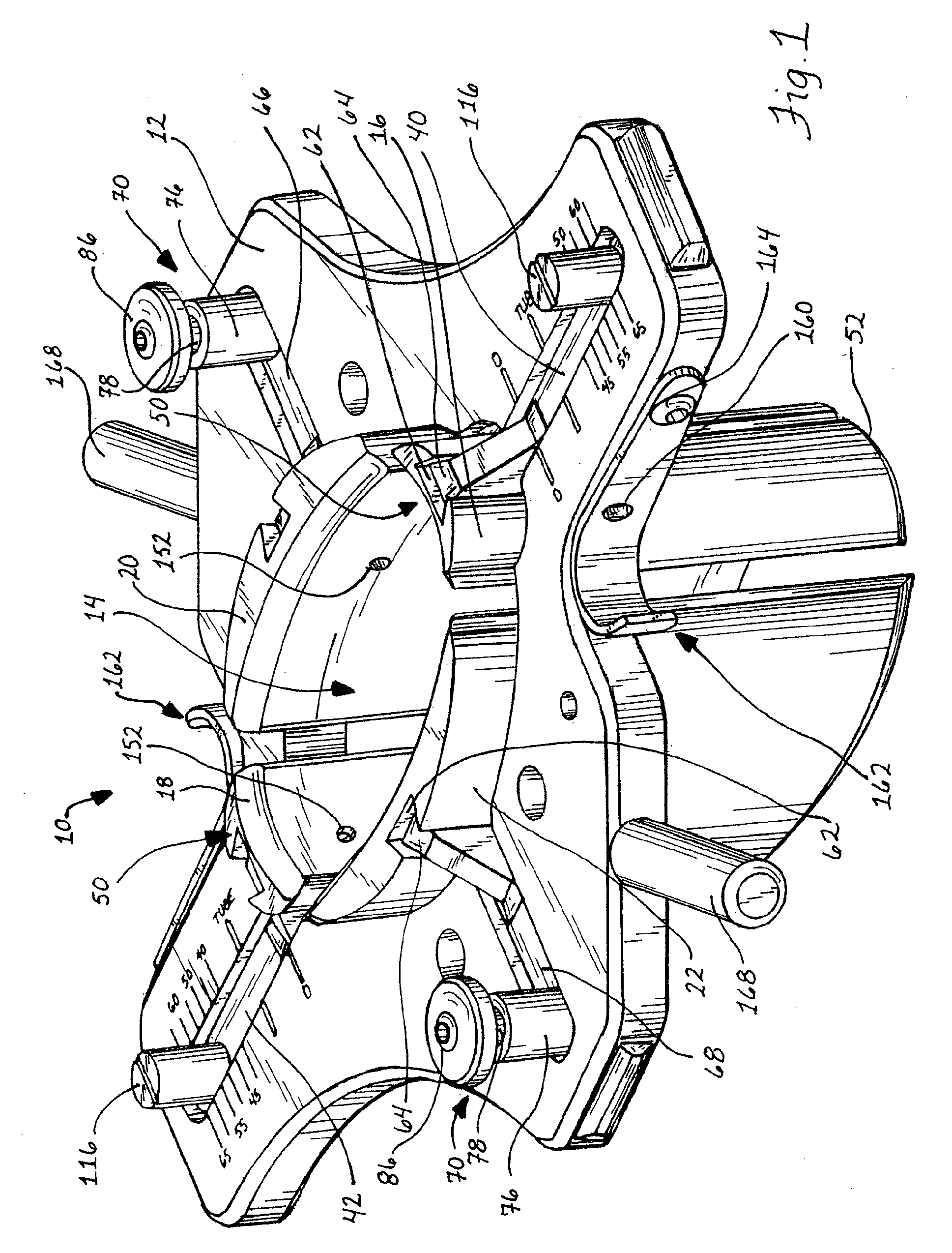
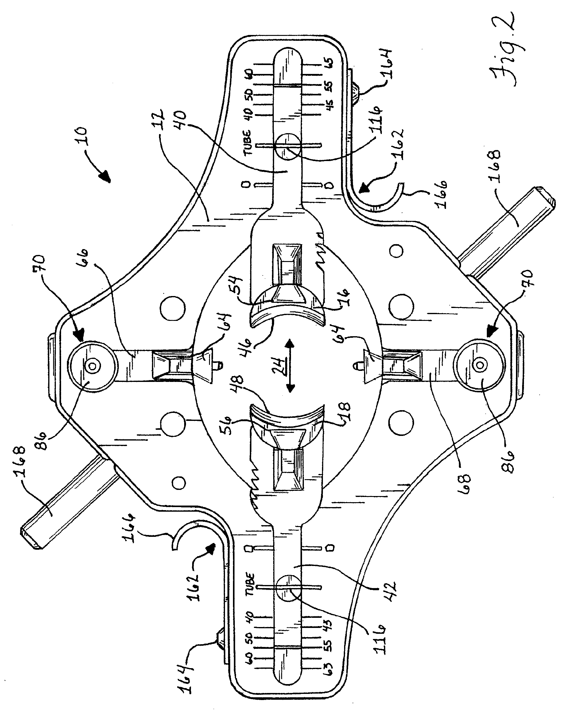
[0052]In FIG. 1, an access retractor generally designated 10 is depicted in the fully retracted or open position thereof. The retractor 10 includes a frame or body 12 having a large retraction opening 14 centrally located for viewing the surgical site. Inside the viewing window 14 are located a number of tissue engaging members, such as in the form of retraction blades 16, 18, 20, and 22. To keep gaps between adjacent, retracted blades to a minimum, it is preferred to undertake the retraction procedure in different stages so that retraction of an incision occurs sequentially with the preferred retractor 10 described herein. In the illustrated and preferred form, it is the narrower blades 16 and 18 disposed opposite from each other across the retraction opening 14 that are retracted during the first or initial stage of the retraction procedure and the wider blades 20 and 22 disposed opposite from each other across the retraction opening 14 that are retracted during the second or fina...

second embodiment

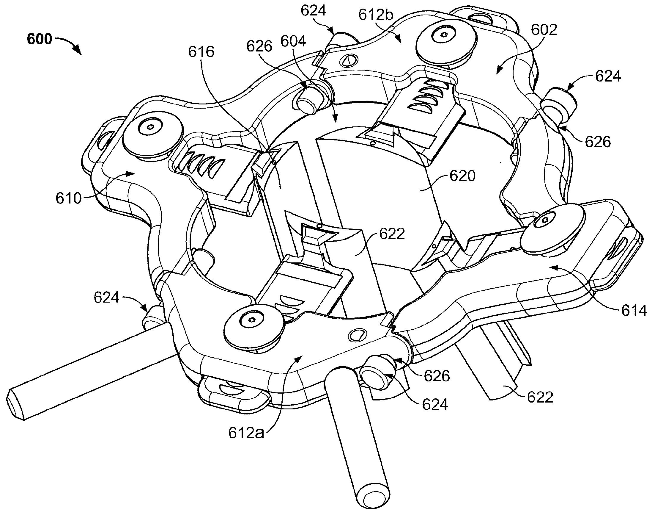
[0075]Turning now to a second embodiment, the access retractor 200 of FIGS. 15-32 is similar to the access retractor 10 of FIGS. 1-7 and 12-14, in that it comprises a generally planar body or frame 202 having a central, oblong or ovular opening 204. Opposing sliders 238, 240 and 242, 244 that slide in through slots 208 and 210 formed in both a longitudinal direction and a transverse direction. A first set of tissue engaging members, in this example comprising narrow blades 216 and 218, are releasably connected to associated sliders 238 and 240, as illustrated in FIG. 15-17, 19 and 20. A second set of tissue engaging members, in this example comprising wide blades 220 and 222, are releasably connected to associated sliders 242 and 244, as illustrated in FIGS. 19 and 20.

[0076]One difference between the first embodiment of the access retractor 10 and the second embodiment of the access retractor 200 is that the latter uses a ratchet mechanism associated with each of the sliders 238, 24...


PUM


Abstract

A retraction apparatus and method are disclosed that provide optimized access to a surgical site. In one form, a retraction frame has a retraction opening with two sets of blades operating therein. The blades are used to sequentially retract the tissue from about an incision. The sequential retraction of the blades generates only narrow gaps between the blades so that tissue and blood encroachment during the surgical procedure are minimized.

Description

RELATED APPLICATIONS[0001]This application is a continuation of U.S. Utility application Ser. No. 11 / 539,224 filed on Oct. 6, 2006, which claims priority to U.S. Provisional Application No. 60 / 761,559 filed on Jan. 23, 2006; and which are hereby incorporated herein by reference in their entirety.FIELD OF THE INVENTION[0002]The invention relates generally to a retractor and method for providing access to a surgical site and, more particularly, a retractor and method for retracting tissue during a surgical procedure.BACKGROUND OF THE INVENTION[0003]While incisions are required during surgical procedures to gain access to the surgical site, such incisions can cause damage, injury, and trauma to the patient's body. To avoid causing unnecessary damage, it is preferable to make the incisions as small as possible, while retaining a clear view of the surgical site. Retractors are used to maximize the viewing range of incisions, thereby allowing the surgeon to minimize damage.[0004]In additi...

Claims


Application Information

Patent Timeline
Patent Type & Authority Applications(United States)
IPC IPC(8): A61B1/32
CPCA61B1/32A61B17/0293A61B17/025A61B17/02
Inventor GEPHART, MATTHEW P.BERMAN, PHILIP J.
Owner XTANT MEDICAL HLDG INC
Why Eureka
Try Eureka