Method for manufacturing cylindrical battery and groove-forming processing device of cylindrical battery

a technology of cylindrical batteries and processing devices, which is applied in the direction of cell components, manufacturing tools, cell component details, etc., can solve the problems of insufficient method and increase in battery costs, and achieve the effects of stably performing the groove-forming processing, simple device structure, and simple tooling chang

Inactive Publication Date: 2009-06-18
PANASONIC CORP
View PDF5 Cites 12 Cited by
  • Summary
  • Abstract
  • Description
  • Claims
  • Application Information

AI Technical Summary

Benefits of technology

[0021]Furthermore, when the rotation driving means rotates the core and the receiving die is rotatable, the battery case is driven to rotate at the vicinity of a processed portion from the side of the core which receives pressure by the groove-forming roller during the processing. Thus, torsion moment does not act on the battery case by rotational driving force. Accordingly, even if the diameter of the battery case is large and the battery case is rotated at high speed, there is no fear that torsion or buckling occurs in the battery case so that it is possible to stably perform the groove-forming processing.
[0022]Furthermore, when the roller push-in means pushes the groove-forming roller into from the same position by the same push-in amount even when the diameter of the battery case varies and the groove-forming roller is exchangeable in accordance with variation in the diameter of the battery case, it is not necessary to change adjustment except for exchanging the core and the groove-forming roller even if the diameter of the battery case varies. Therefore, the structure of the device becomes simple and a tooling change is extremely simply carried out, and hence it is possible to efficiently manufacture various sizes of batteries at low costs.
[0023]When the receiving die is disposed in such a manner that the top face thereof is flush with a base plate and the push-up means can move the receiving die up, and the core, the rotation driving means, the groove-forming roller, and the roller push-in means are provided in a elevating frame which is vertically movable along a supporting frame erected on the base plate, the battery case is smoothly supplied from the base plate to the receiving die for processing. Furthermore, it is possible to easily correspond to variation in the height of the battery case by adjusting the height position of the elevating frame, so that it is possible to secure high productivity by the device with simple structure.
[0024]The roller push-in means may include a plate cam provided in a rotary shaft which rotates in conjunction with the push-up means and a movable member on which a cam follower making contact with the plate cam is fixed, the movable member being supported by the elevating frame movably in the radial direction of the core. In addition, the movable member supports the groove-forming roller. In this case, it is possible to allow the groove-forming roller to carry out stable push-in operation by simple structure, and hence stably perform the groove-forming processing.
[0025]When the backup roller which comes into contact with the outside periphery of the battery case on the opposite side of the groove-forming roller to prevent the occurrence of bending of the battery case by receiving the press force of the groove-forming roller is rotatably provided in a fixed position, the backup roller prevents the battery case from being bent by receiving the press force of the groove-forming roller. The backup roller acts so as to turn the escape of the battery case in the radial direction by the press force of the groove-forming roller toward the axial direction of the battery case. Accordingly, since the battery case after the completion of the groove-forming processing has only internal residual stress in the axial direction and does not have internal residual stress in the radial direction, its shape does not change in the radial direction due to the internal residual stress. Therefore, it is possible to secure a required shape with high accuracy.
[0026]Furthermore, when a plurality of backup rollers is provided in positions symmetric with respect to an extension line passing through respective axis of the groove-forming roller and the battery case, the battery case can be smoothly rotated while the plurality of backup rollers further certainly prevents the battery case from being bent by receiving the press force of the groove-forming roller. Therefore, it is possible to smoothly turn the escape of the battery case in the radial direction by the press force of the groove-forming roller toward the axial direction of the battery case.

Problems solved by technology

Thus, in order to manufacture various sizes of batteries, it is necessary to prepare the groove-forming processing devices on a battery size basis and hence there is a problem that increase in an investment in facilities brings about increase in the costs of the battery.
In addition to this, it is necessary to exchange the receiving dies in accordance with the heights and exchange operation is difficult and inefficient due to its structure so that the processing method cannot sufficiently solve the foregoing problems.

Method used


Image

  • Method for manufacturing cylindrical battery and groove-forming processing device of cylindrical battery
  • Method for manufacturing cylindrical battery and groove-forming processing device of cylindrical battery
  • Method for manufacturing cylindrical battery and groove-forming processing device of cylindrical battery

Examples


Embodiment Construction

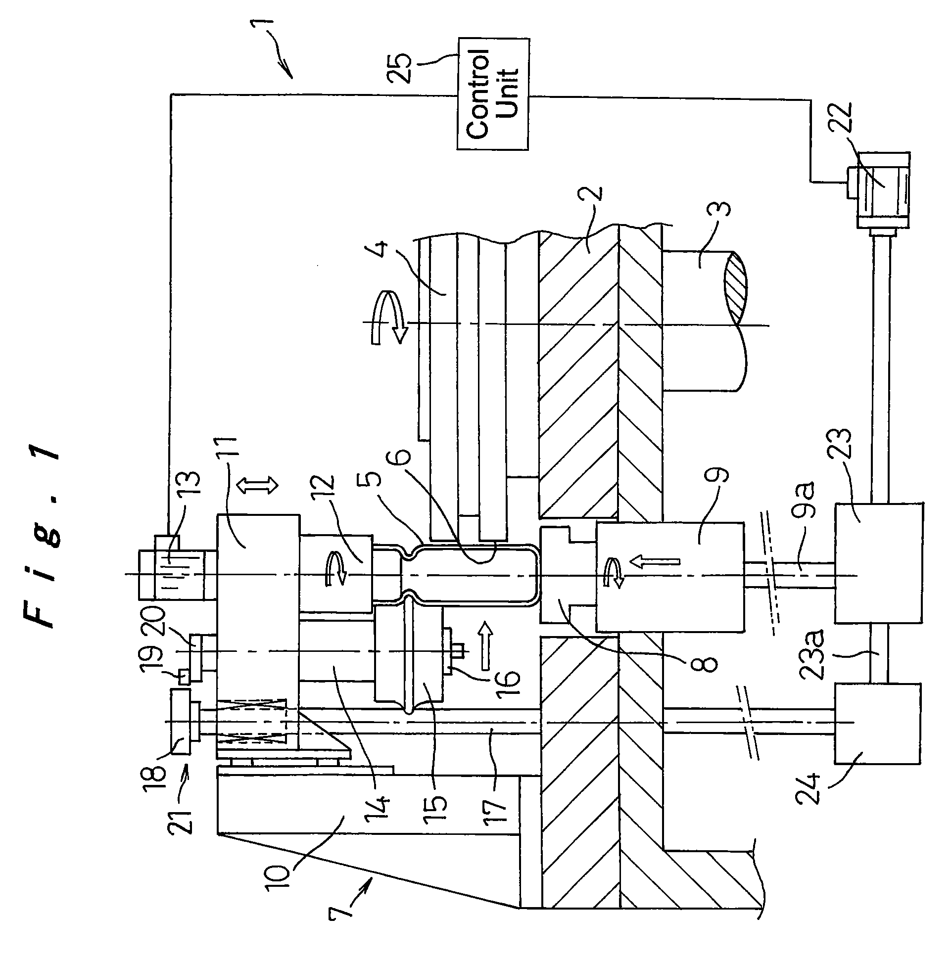
[0036]A first embodiment of the present invention will be described in detail with reference to the drawings. FIG. 1 is a longitudinal sectional view of a groove-forming processing station (groove-forming processing device) 7 in a manufacturing apparatus 1 of a cylindrical battery. In FIG. 1, reference numeral 2 refers to a base plate, and a rotor 4 which is intermittently rotated by a rotary shaft 3 is disposed on the center of the top of the base plate 2. In the outside periphery of the rotor 4, a plurality of holder sections 6 for holding battery cases 5 of the cylindrical batteries is disposed in a circumferential direction at regular intervals and the rotor 4 is intermittently rotated at the disposition interval of the holder sections 6. In each stop position of the holder sections 6 of the rotor 4, there is a station for carrying out each manufacturing process of the cylindrical battery. For example, a carrying-in station which carries the battery case 5 in the holder section ...


PUM

PropertyMeasurementUnit
diameteraaaaaaaaaa
thicknessaaaaaaaaaa
press forceaaaaaaaaaa

Abstract

A method for manufacturing a cylindrical battery includes allowing a cylindrical battery case (5) with a bottom to contain an electrode plate group, carrying out a groove-forming processing on an outside periphery of an opening of the battery case, disposing a sealing plate in the opening of the battery case through a gasket, and crimping and sealing the end of the opening of the battery case. In a groove-forming processing process in which the battery case is rotated and a rotatable groove-forming roller (15) comes into contact with and is gradually pushed into the outside periphery of the opening of the battery case in a state where a core (12) corresponding to the diameter of the opening of the battery case is fitted into the opening of the battery case to support the battery case from the inner peripheral side, a rotational speed is increased in accordance with increase in the diameter of the battery case so that the push-in amount of the groove-forming roller per unit rotation perimeter and per unit of time approximately becomes a certain value even if the size of the diameter of the battery case varies. Thus, a common groove-forming processing device can carry out the groove-forming processing on battery cases of different battery sizes to manufacture cylindrical batteries.

Description

TECHNICAL FIELD[0001]The present invention relates to a method for manufacturing a cylindrical battery and a device used for the same, and in particular, relates to a manufacturing method for carrying out groove-forming processing on a battery case in the shape of a cylinder with a bottom and a groove-forming processing device.BACKGROUND ART[0002]In recent years, electronic equipment such as an AV device, a personal computer, and a portable communication device is rapidly made portable and cordless, and a hermetically sealed battery which has high energy density and a superior load characteristic is demanded as a driving power source of the electronic equipment and other motive devices. In particular, a lithium battery comes under the spotlight because of such many features that its energy density and voltage is high and shelf life is long.[0003]For example, in order to form a cylindrical lithium battery, an electrode plate group is formed by winding a positive electrode plate and a...

Claims


Application Information

Patent Timeline
Patent Type & Authority Applications(United States)
IPC IPC(8): B32B37/00B28B1/20H01M50/167
CPCB21D17/04B29C57/00H01M2/022Y10T29/4911H01M2/0408Y10T29/53139Y10T29/53687H01M2/0225Y02E60/10H01M50/56H01M50/107H01M50/167H01M10/0404H01M50/213H01M50/171
Inventor TERAMOTO, KAZUTAKA
Owner PANASONIC CORP
Why Eureka
Try Eureka