Lancing devices and methods

a technology of lancing device and splint, which is applied in the field of lancing device, can solve the problems of both vibration and sound the relatively large size of the lancing device, and the cost of manufacturing and operation, and achieves the effects of low cost of production, minimal vibration and/or sound during use, and easy operation

Inactive Publication Date: 2009-11-12
LIFESCAN IP HLDG LLC
View PDF37 Cites 104 Cited by
  • Summary
  • Abstract
  • Description
  • Claims
  • Application Information

AI Technical Summary

Benefits of technology

[0005]Applicants have recognized a need for a lancing device that is relatively inexpensive to manufacture and easily operated. Such device must also produce a minimal amount of vibration and / or sound during use, thereby decreasing the level of pain perceived by a user.

Problems solved by technology

The arming and launching of conventional lancing devices involves a multitude of complicated mechanisms that result in the lancing device being relatively large in size, costly to manufacture and cumbersome to operate.
In addition, the operation of conventional lancing device mechanisms can induce both vibrations within the lancing device and sounds that increase the level of pain perceived by a user.

Method used


Image

  • Lancing devices and methods
  • Lancing devices and methods
  • Lancing devices and methods

Examples


Embodiment Construction

in conjunction with the accompanying drawings that are first briefly described.

BRIEF DESCRIPTION OF THE FIGURES

[0013]The accompanying drawings, which are incorporated herein and constitute part of this specification, illustrate presently preferred embodiments of the invention, and, together with the general description given above and the detailed description given below, serve to explain features of the invention (wherein like numerals represent like elements), of which:

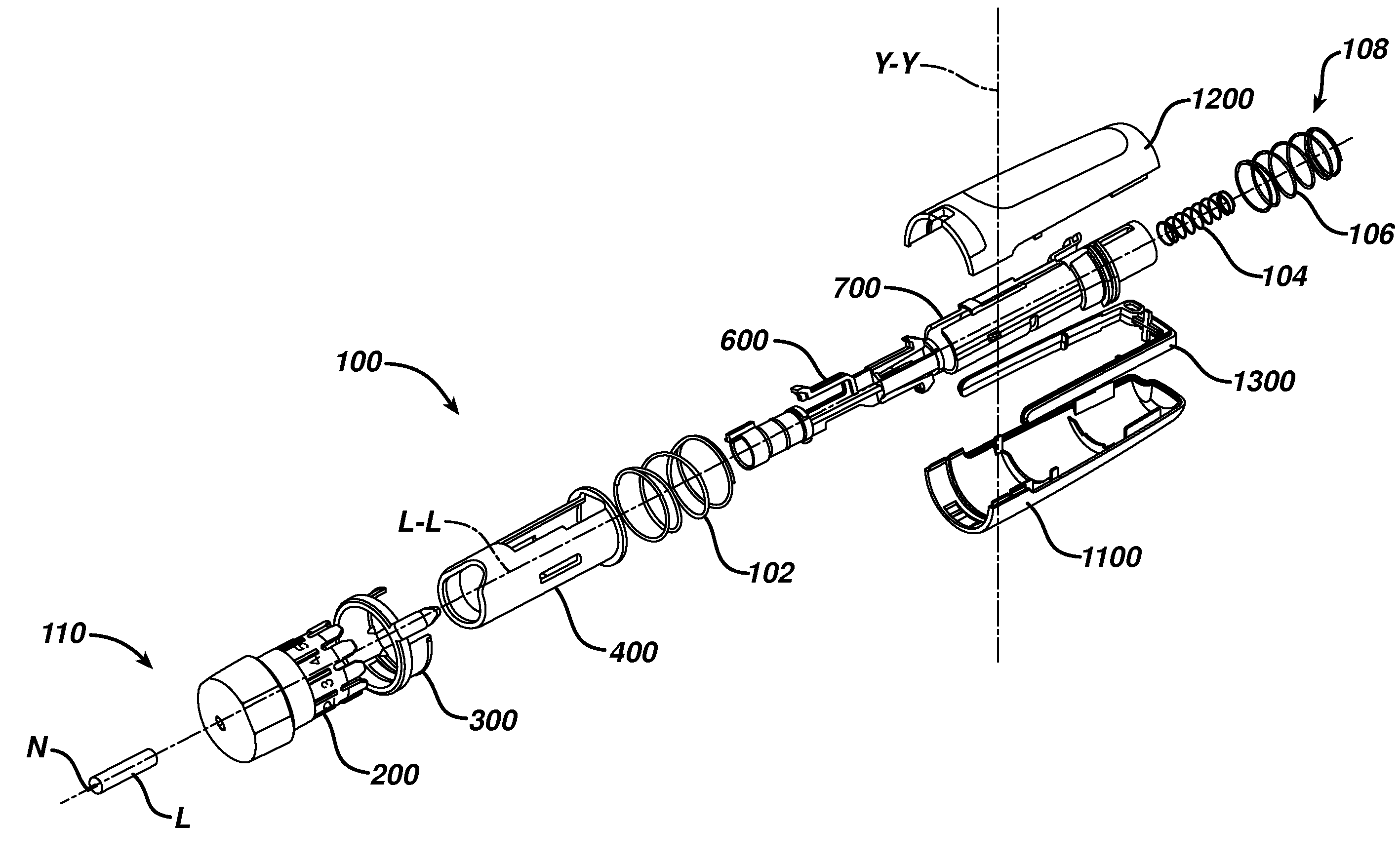
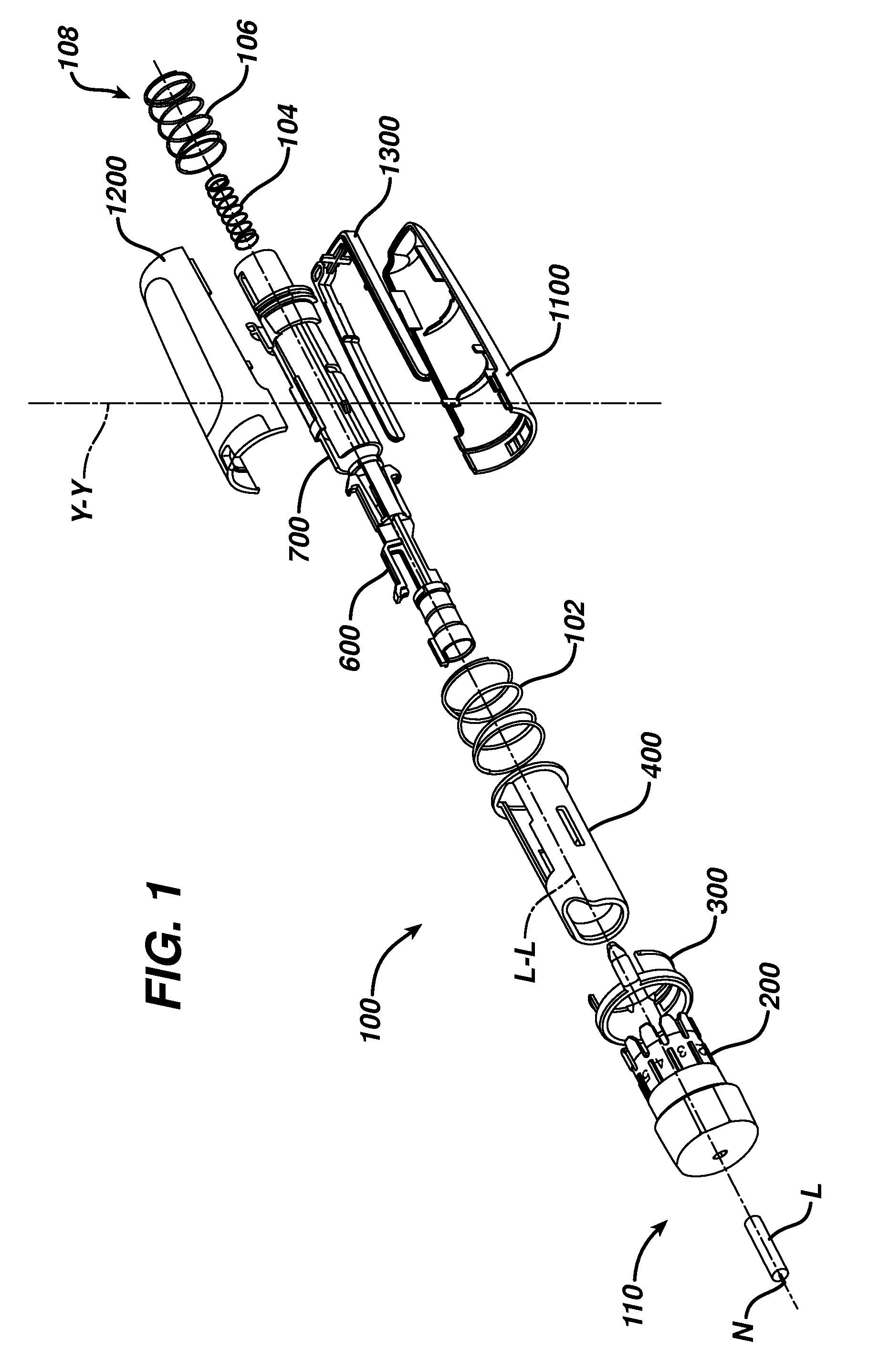
[0014]FIG. 1 is an exploded view of a lancing device, according to an exemplary embodiment described and illustrated herein.

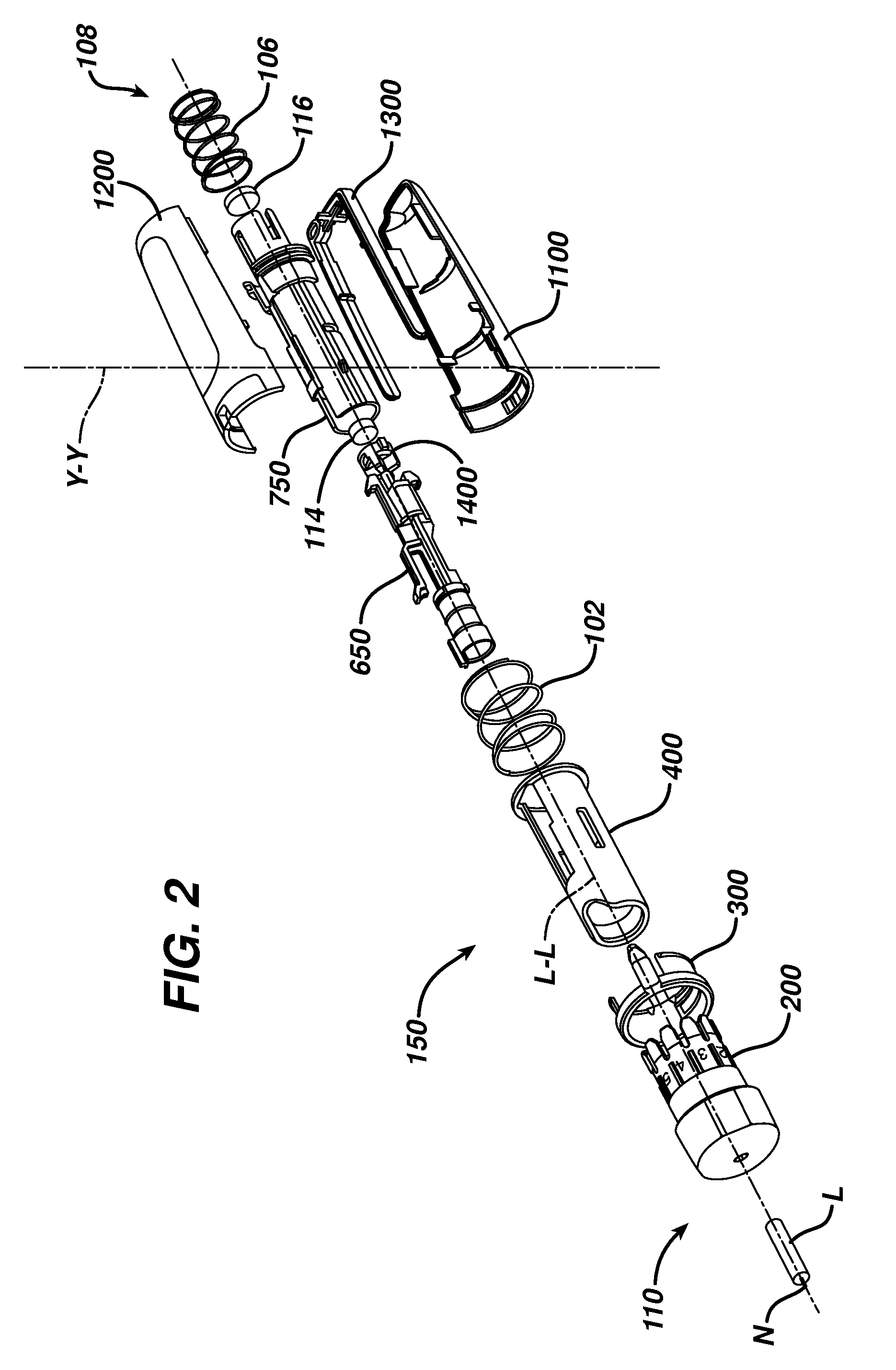
[0015]FIG. 2 is an exploded view of another lancing device, according to an exemplary embodiment described and illustrated herein.

[0016]FIGS. 3A-3C are perspective views of a lancet depth adjustment member and cap, according to an exemplary embodiment described and illustrated herein.

[0017]FIGS. 4A-4B are perspective views of a lock ring, according to an exemplary embodiment described and illus...


PUM


Abstract

Described and illustrated herein is an exemplary lancing device. The exemplary lancing device comprises: a first housing having spaced apart proximal and distal ends disposed along a longitudinal axis; a chassis disposed in the first housing in a fixed relationship with the first housing; a movable member disposed in the chassis and configured for movement along the longitudinal axis and in the first housing; a lancet coupled to the movable member; and a lancet depth adjustment member retained by both the first and chassis so that the lancet depth adjustment member is rotatable relative to both housings to provide for a plurality of stop surfaces to the movable member. Other embodiments and methods are also described.

Description

PRIORITY[0001]This application claims the benefits of priority of U.S. Provisional Patent Application Ser. No. 61 / 052,088 filed on May 9, 2008.BACKGROUND[0002]Conventional lancing devices generally have a rigid housing, various operating mechanisms and a lancet that can be armed and launched so as to briefly protrude from one end of the lancing device. For example, conventional lancing devices can include a lancet that is mounted within a rigid housing such that the lancet is movable relative to the rigid housing along a longitudinal axis thereof. Typically, the lancet is spring loaded and launched, upon release of the spring, to penetrate (i.e., “lance”) a target site (e.g., a dermal tissue target site). A bodily fluid sample (e.g., a whole blood sample) can then be expressed from the penetrated target site for collection and analysis.[0003]Conventional lancing devices typically require a user to arm the lancing device, urge the lancing device against a target site, and then press ...

Claims


Application Information

Patent Timeline
Patent Type & Authority Applications(United States)
IPC IPC(8): A61B5/151
CPCA61B5/15186A61B5/1411A61B5/150022A61B5/15019A61B5/150412A61B5/150503A61B5/150549A61B5/150618A61B5/150717A61B5/150824A61B5/15109A61B5/15117A61B5/15123A61B5/1513A61B5/1519A61B5/15194
Inventor FAULKNER, ALLAN JAMESFOLEY, NICHOLASCROSLAND, DAVID COLINYOUNG, MATTHEW JAMESTRICKETT, PAUL
Owner LIFESCAN IP HLDG LLC
Why Eureka
Try Eureka