Illuminated toy balloon with stand

a toy balloon and stand technology, applied in the field of illuminated toy balloons, can solve the problem of no present way in which such balloons are self-supporting

Inactive Publication Date: 2009-12-10
CHEM LIGHT
View PDF10 Cites 22 Cited by
  • Summary
  • Abstract
  • Description
  • Claims
  • Application Information

AI Technical Summary

Benefits of technology

[0007]A stop valve is in flow communication with the hollow filler tube and is disposed in the plug. A light assembly includes a battery and at least one light element electrically connected to the battery affixed in proximity to the stop valve. The inflator is inserted into the toy balloon with the plug in the neck of the balloon and the bottom of the hollow filler tube extending below the neck of the balloon for filling the balloon with a gas through the hollow filler tube. The stop valve prevents gas from escaping the balloon and the balloon can float freely in the air without support.
[0008]A rigid support is operably connected to the inflator at one end and is insertable into the ground at the other end. The support provides an upstanding orientation of the balloon when filled with a lighter-than-air gas or with air. The ground insertion portion of the support can include a pointed, stake-like end on the support. Alternately, a flange can be mounted to a lower end of the rigid support and two pointed, stake-like elements can de[end from the flange to secure the balloon and support in the ground.

Problems solved by technology

While such illuminated balloons are known, there is no present way in which such balloons are self-supporting.

Method used


Image

  • Illuminated toy balloon with stand
  • Illuminated toy balloon with stand
  • Illuminated toy balloon with stand

Examples


Embodiment Construction

[0028]While the present invention is susceptible of embodiment in various forms, there is shown in the drawings and will hereinafter be described a presently preferred embodiment with the understanding that the present disclosure is to be considered an exemplification of the invention and is not intended to limit the invention to the specific embodiment illustrated.

[0029]It should be further understood that the title of this section of this specification, namely, “Detailed Description Of The Invention”, relates to a requirement of the United States Patent Office, and does not imply, nor should be inferred to limit the subject matter disclosed herein.

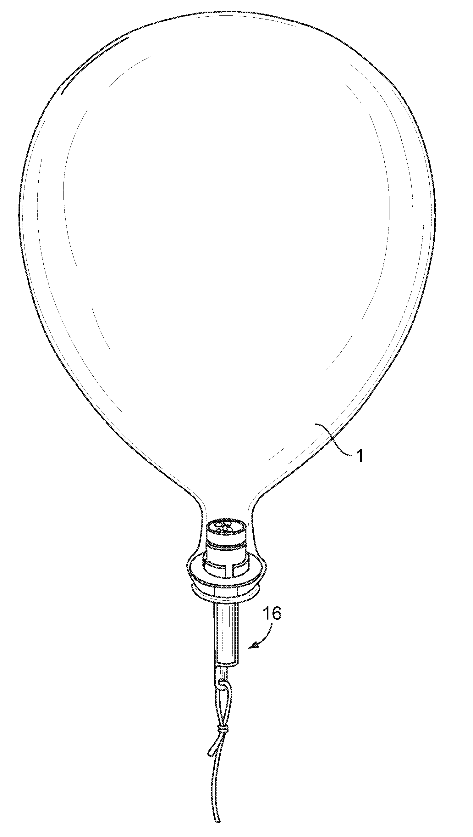
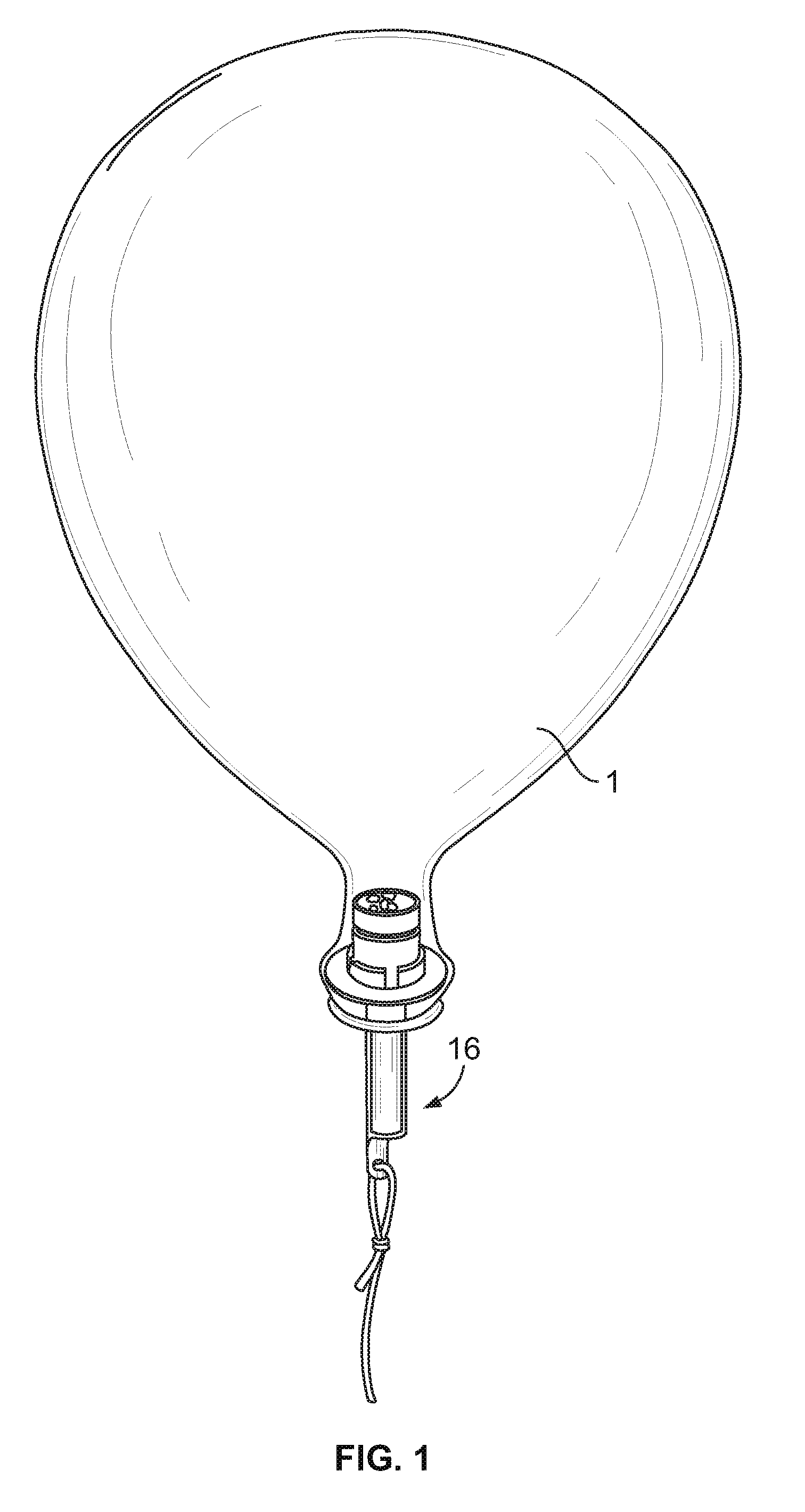
[0030]Referring to FIG. 1, the present device 16 is inserted into the neck of a balloon, with a cord 3 attached to the device restraining the balloon. The balloon is obviously filled with a gas, which may be air, helium, or similarly inert gasses, in the case of balloons used as toys, on account of safety concerns. In other applications,...


PUM


Abstract

An apparatus for illuminating the interior of a balloon, and a support for the apparatus and the balloon. The illuminating apparatus includes a plug with an integrally-formed radially extending flange insertable within the balloon neck. A hollow filler tube depends from the flange. A light element is affixed to the plug and disposed within the neck. A battery is electrically connected to the light element. Switching is provided to turn the lighting element on and off. A rigid support is operably connected to the inflator and is insertable into the ground to provide an upstanding orientation of the balloon when filled with a lighter-than-air gas or with air.

Description

CROSS-REFERENCE TO RELATED APPLICATION DATA[0001]This application is a continuation-in-part of U.S. patent application Ser. No. 12 / 032,876, filed Feb. 18, 2008, which is a continuation of U.S. patent application Ser. No. 10 / 904,486, filed Nov. 12, 2004, now U.S. Pat. No. 7,344,267.BACKGROUND OF THE INVENTION[0002]The present invention relates to illuminated toy balloons. More particularly, the present invention relates to self-supporting illuminated balloons. The use of lights in association with balloons is well known. Examples include U.S. Pat. Nos. 6,390,651 and 5,215,492. Also well known is the use of chemiluminescent materials or light sticks that produce light by chemical reaction which may be inserted into balloons.[0003]The present invention is an improvement over the prior art in which an inexpensive, self-powered apparatus is inserted into the neck of a balloon, which contains a small, energy-efficient light source powered by a battery, and which has the ability to switch ...

Claims


Application Information

Patent Timeline
Patent Type & Authority Applications(United States)
IPC IPC(8): F21L4/02
CPCA63H27/10F21Y2101/02F21V3/023A63H2027/1058F21Y2115/10
Inventor SCHRIMMER, MICHAEL L.
Owner CHEM LIGHT
Why Eureka
Try Eureka