Frequency calibration loop circuit

a loop circuit and frequency technology, applied in the direction of electrical equipment, radio transmission, automatic control, etc., can solve the problem of taking an excessive amount of time to shift to the target frequency band

Inactive Publication Date: 2010-06-03
ELECTRONICS & TELECOMM RES INST
View PDF2 Cites 23 Cited by
  • Summary
  • Abstract
  • Description
  • Claims
  • Application Information

AI Technical Summary

Benefits of technology

[0009]An aspect of the present invention provides a frequency calibration ...

Problems solved by technology

Thus, if the input bits for the frequency calibration of the oscillator are...

Method used


Image

  • Frequency calibration loop circuit
  • Frequency calibration loop circuit
  • Frequency calibration loop circuit

Examples


Embodiment Construction

[0024]Exemplary embodiments of the present invention will now be described in detail with reference to the accompanying drawings. The invention may however be embodied in many different forms and should not be construed as limited to the embodiments set forth herein. Rather, these embodiments are provided so that this disclosure will be thorough and complete, and will fully convey the scope of the invention to those skilled in the art. In the drawings, the shapes and dimensions may be exaggerated for clarity, and the same reference numerals will be used throughout to designate the same or like components.

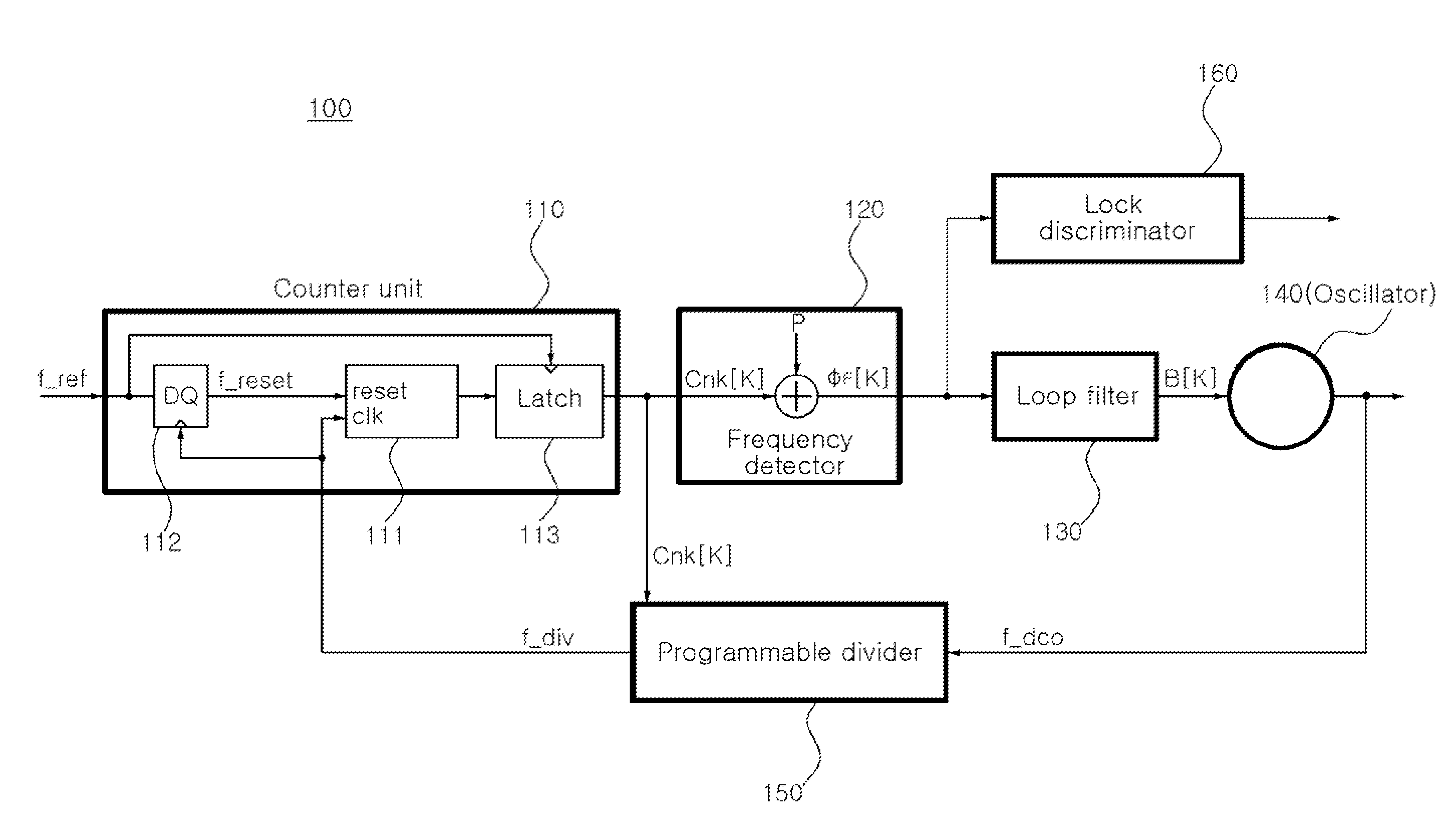
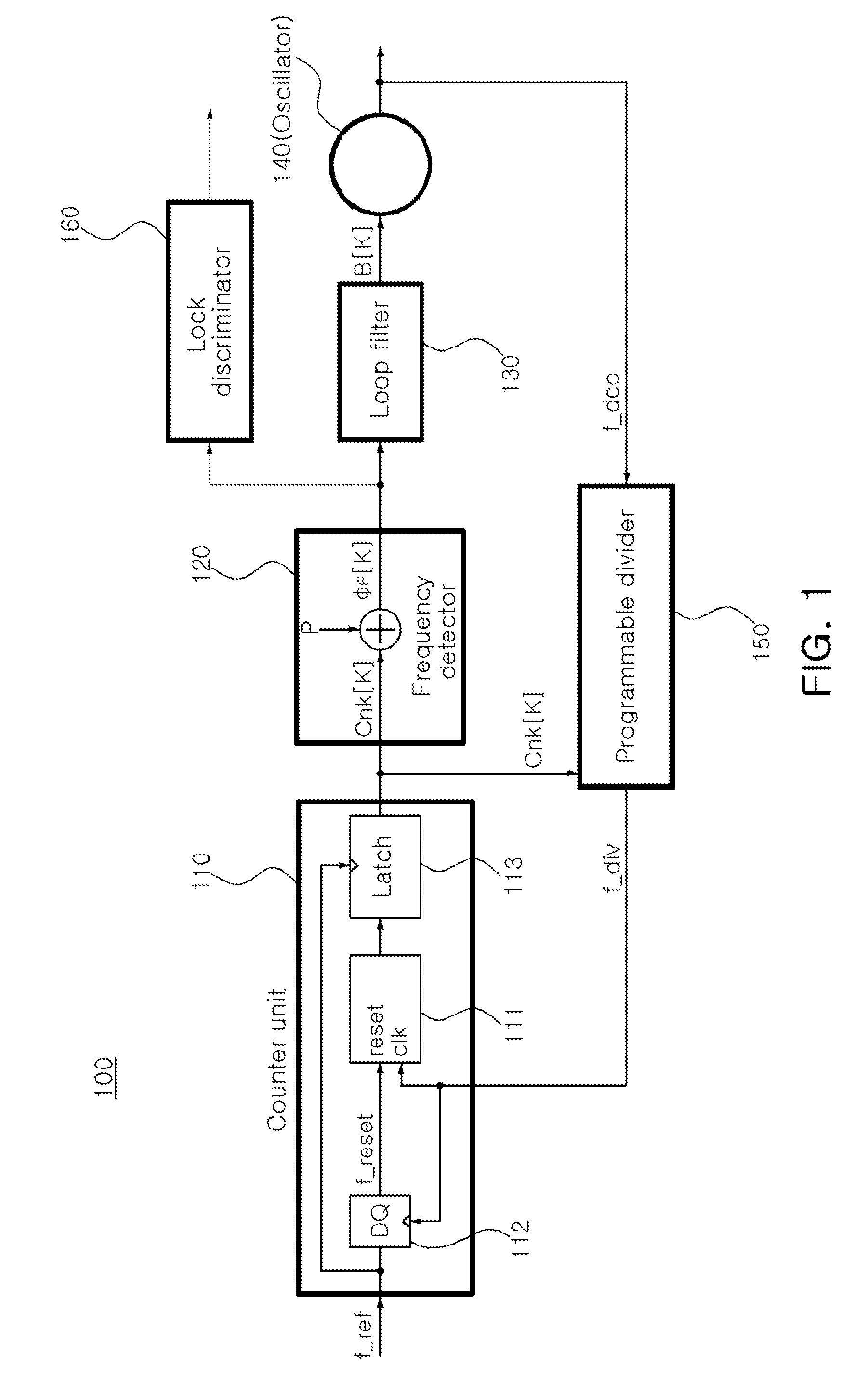
[0025]FIG. 1 is a schematic block diagram of a frequency calibration loop circuit according to an exemplary embodiment of the present invention.

[0026]With reference to FIG. 1, a frequency calibration loop circuit 100 according to an exemplary embodiment of the present invention includes a counter 110, a frequency detector 120, an oscillator 140, and a programmable divider 150 so as ...


PUM


Abstract

A frequency calibration loop circuit having a pre-set frequency channel word (FCW) command value, a bit inputted to obtain a target frequency in an oscillator and a pre-set minimum division ratio n (n is a constant) of a programmable divider, includes: an oscillator adjusting a oscillation frequency according to control value; a programmable divider dividing the oscillation frequency according to a division ratio; a counter counting the number of clocks of the divided frequency by using a reference frequency; and a frequency detector outputting a value obtained by subtracting the number of the counted clocks from a reference comparison value, a value obtained by dividing a Frequency Channel Word (FCW) command value by a minimum division ratio of the programmable divider, as the control value of the oscillator.

Description

CROSS-REFERENCE TO RELATED APPLICATIONS[0001]This application claims the priorities of Korean Patent Application Nos. 10-2008-0121232 filed on Dec. 2, 2008 and 10-2009-0023897 filed on Mar. 20, 2009, in the Korean Intellectual Property Office, the disclosure of which is incorporated herein by reference.BACKGROUND OF THE INVENTION[0002]1. Field of the Invention[0003]The present invention relates to a frequency calibration loop circuit applicable to a frequency synthesizer and, more particularly, to a frequency calibration loop circuit capable of rapidly shifting the oscillation frequency of an oscillator to a target frequency band desired by a user.[0004]2. Description of the Related Art[0005]A frequency synthesizer is commonly used to generate a stable frequency for transmission and reception in the mobile communications sector.[0006]A frequency calibration loop circuit enables the oscillation frequency of an oscillator in a broadband frequency synthesizer to be rapidly shifted to a...

Claims


Application Information

Patent Timeline
IPC IPC(8): H03L7/00
CPCH03L2207/50H03L7/181Y10S331/02
Inventor MIN, BYUNG HUNLEE, JA YOLKIM, SEONG DOKIM, CHEON SOOYU, HYUN KYU
Owner ELECTRONICS & TELECOMM RES INST
Why Eureka
Try Eureka