LED retrofit for fluorescent backlit signs

a backlit sign and led technology, applied in lighting support devices, instruments, lighting and heating apparatuses, etc., can solve the problems of more expensive components, more complex assembly, and lower efficiency, and achieve the effect of quick and easy installation

Inactive Publication Date: 2011-01-27
ZIMMERMAN JAMES WILLIAM +2
View PDF11 Cites 38 Cited by
  • Summary
  • Abstract
  • Description
  • Claims
  • Application Information

AI Technical Summary

Benefits of technology

[0018]The current invention can be used in OEM applications as well a retrofit applications. In the case of retrofit applications, simple adapters mounted to the lightweight frame provide a quick and easy

Problems solved by technology

This results in a more complex assembly with more components, more expensive components, and lower efficiency.
Indirect lighting, use of reflectors, lenses, and light pipes can all lead to loss of efficiency relative to direct lig

Method used


Image

  • LED retrofit for fluorescent backlit signs
  • LED retrofit for fluorescent backlit signs
  • LED retrofit for fluorescent backlit signs

Examples


Embodiment Construction

[0024]The following detailed description is of the best presently contemplated modes of carrying out the invention. This description is not to be taken in a limiting sense, but is made merely for the purposes of illustrating general principles of embodiments of the invention.

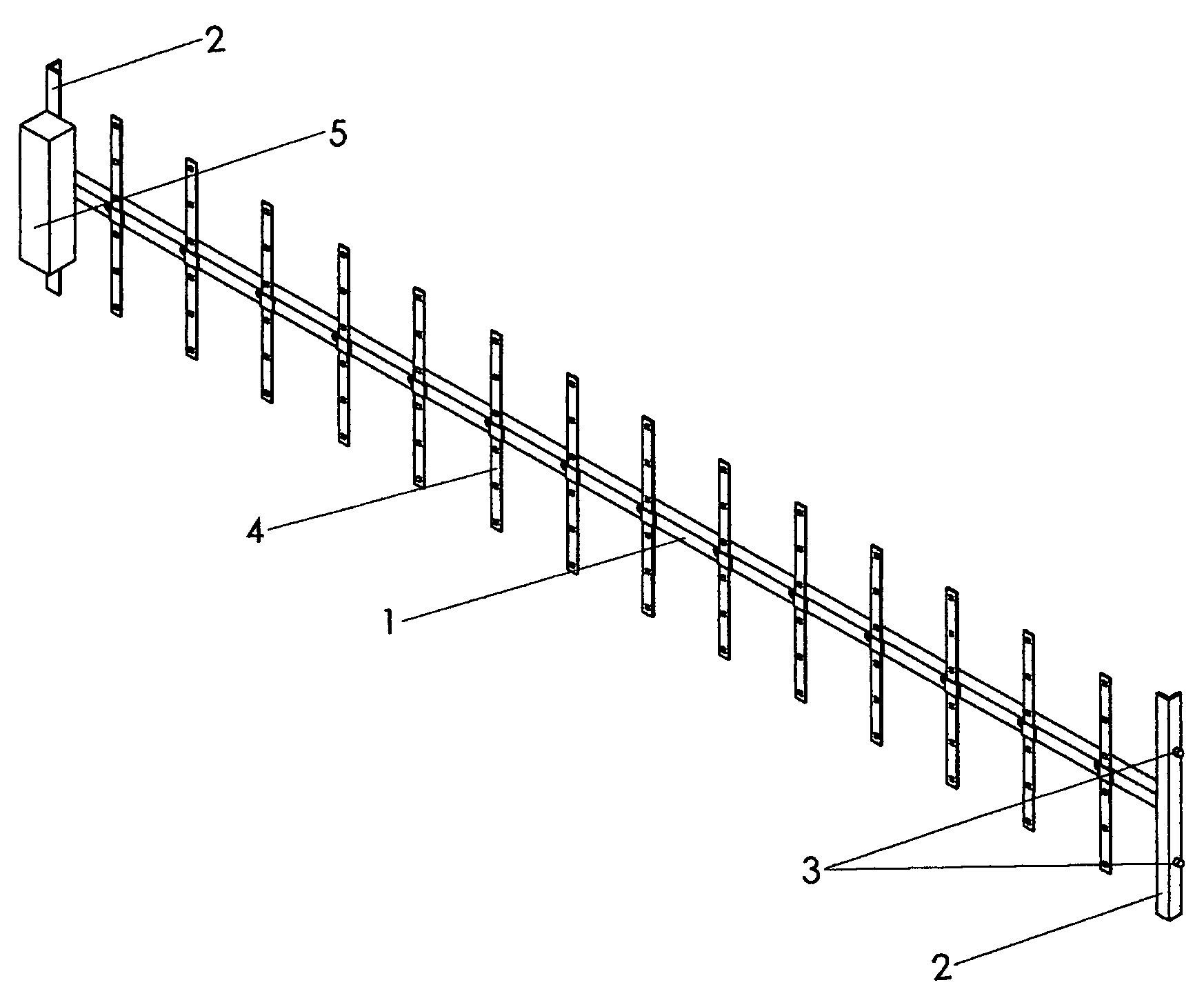
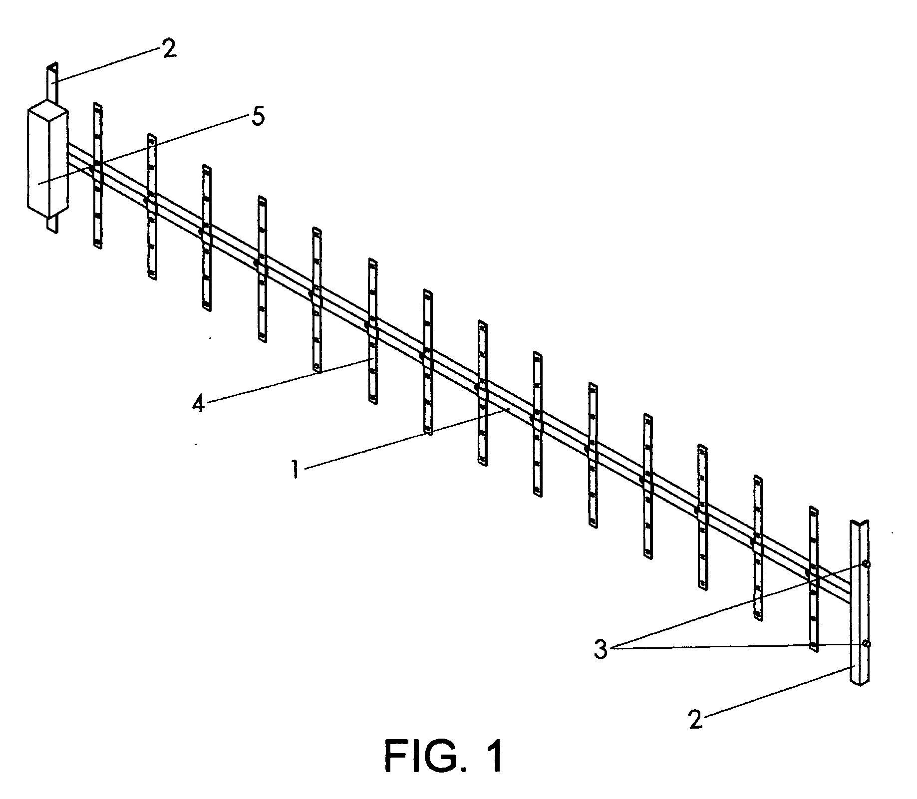
[0025]FIG. 1 shows assembly typifying an embodiment of the invention tailored to replace two single pin base fluorescent tubes with LED lighting. The frame consists of a long length of extruded aluminum angle 1 to the ends of which are attached two short lengths of extruded aluminum angle 2 using a single fastener such as a pop rivet for each. FIG. 3 shows in greater detail the short length of extruded aluminum angle 2 into which is pressed the single pin base fluorescent tube adapter 3. The entire assembly is pressed into the two sets of fluorescent tube receptacles simultaneously in a manner similar to which the fluorescent tubes are installed. The assembly is now mechanically secured into the fixture. The ada...


PUM


Abstract

The present invention relates to an LED assembly designed to supplant fluorescent tubes, comprising: an array of standardized LED modules affixed to a lightweight frame resulting in a uniform two dimensional array of LEDs casting their light directly onto a translucent sign panel or, alternatively, a light defusing panel for area lighting. When the application is to retrofit a fixture with fluorescent tubes, the assembly is provided with adapters that attach to the fluorescent tube receptacles.

Description

FIELD OF THE INVENTION[0001]The present invention generally relates to a means of easily replacing the fluorescent lighting in backlit signs with longer lasting, lower maintenance, more power efficient light emitting diode modules.BACKGROUND OF THE INVENTION[0002]Fluorescent backlit street signs have become the street sign of choice at critical intersections around the world. They make it very easy to identify street names at night, which reduces the level of distraction experienced by drivers unfamiliar with the location. This makes for safer intersections. The downside of these signs with fluorescent lights is they must be replaced approximately every eight months. The cost of the fluorescent tubes themselves is not too great, but the cost of the crew and equipment to perform the maintenance adds up. It is also a nuisance to properly dispose of the spent fluorescent bulbs.[0003]It has been recognized that Light Emitting Diodes (LEDs) have the obvious advantage of having a much lon...

Claims


Application Information

Patent Timeline
IPC IPC(8): F21S4/00H01J9/50
CPCF21Y2101/02G09F13/22G09F2013/1895Y10S362/80Y02B20/386F21K9/30G09F2013/225F21K9/20F21Y2115/10Y02B20/30
Inventor ZIMMERMAN, JAMES WILLIAMMYER, JIMMYSANFORD, WILLIAM RAYMOND
Owner ZIMMERMAN JAMES WILLIAM
Why Eureka
Try Eureka