Device for genrating limit torque and rotating device using the same

a technology of limit torque and rotating device, which is applied in the direction of programmable manipulators, slip couplings, yielding couplings, etc., can solve the problems of device damage, device cannot be rotated, and the rotating member cannot be rotated, so as to simplify the structure of the rotating device.

Active Publication Date: 2011-04-07
KOREA INST OF SCI & TECH
View PDF6 Cites 10 Cited by
  • Summary
  • Abstract
  • Description
  • Claims
  • Application Information

AI Technical Summary

Benefits of technology

[0022]The limit torque generating device according to the present invention may be used for a rotating device such as a joint of a robot manipulator, and can generate limit torque with a relatively simple structure.
[0023]Further, when a rotating member of a rotating device comes in contact with a person or an object, a rotational displacement occurs in the limit torque generating device so as to protect the device, which makes it possible to secure the safety of the person or object.
[0024]Further, without an additional unit, the limit torque generating device automatically returns to the initial position, when an external force is eliminated. Therefore, the structure of the rotating device can be simplified, and a separate step for returning to the initial position does not need to be performed.

Problems solved by technology

However, an unexpected external force may be applied to the robot manipulator which comes in contact with the outside during an operation.
On the other hand, the rotating member cannot be rotated because of the interference of the external force.
As a result, torque equal to or greater than limit torque may be applied between the rotating shaft and the rotating member, and the device may be damaged.
Further, when a person or an object comes in contact with the rotating member which is being rotated, the person or object may be hurt or damaged.
However, the conventional rotating device in which a rotational displacement occurs in the rotating shaft and the rotating member has a complex structure, and the weight of the rotating device increases inevitably because of the structure.
Further, the rotating device does not have a function of returning to the initial position, after an external force is eliminated.

Method used


Image

  • Device for genrating limit torque and rotating device using the same
  • Device for genrating limit torque and rotating device using the same
  • Device for genrating limit torque and rotating device using the same

Examples


Embodiment Construction

[0035]Hereinafter, preferred embodiments of the present invention will be described. While the present invention is described with reference to embodiments thereof, the technical idea and the construction and operation of the invention are not limited to the embodiments.

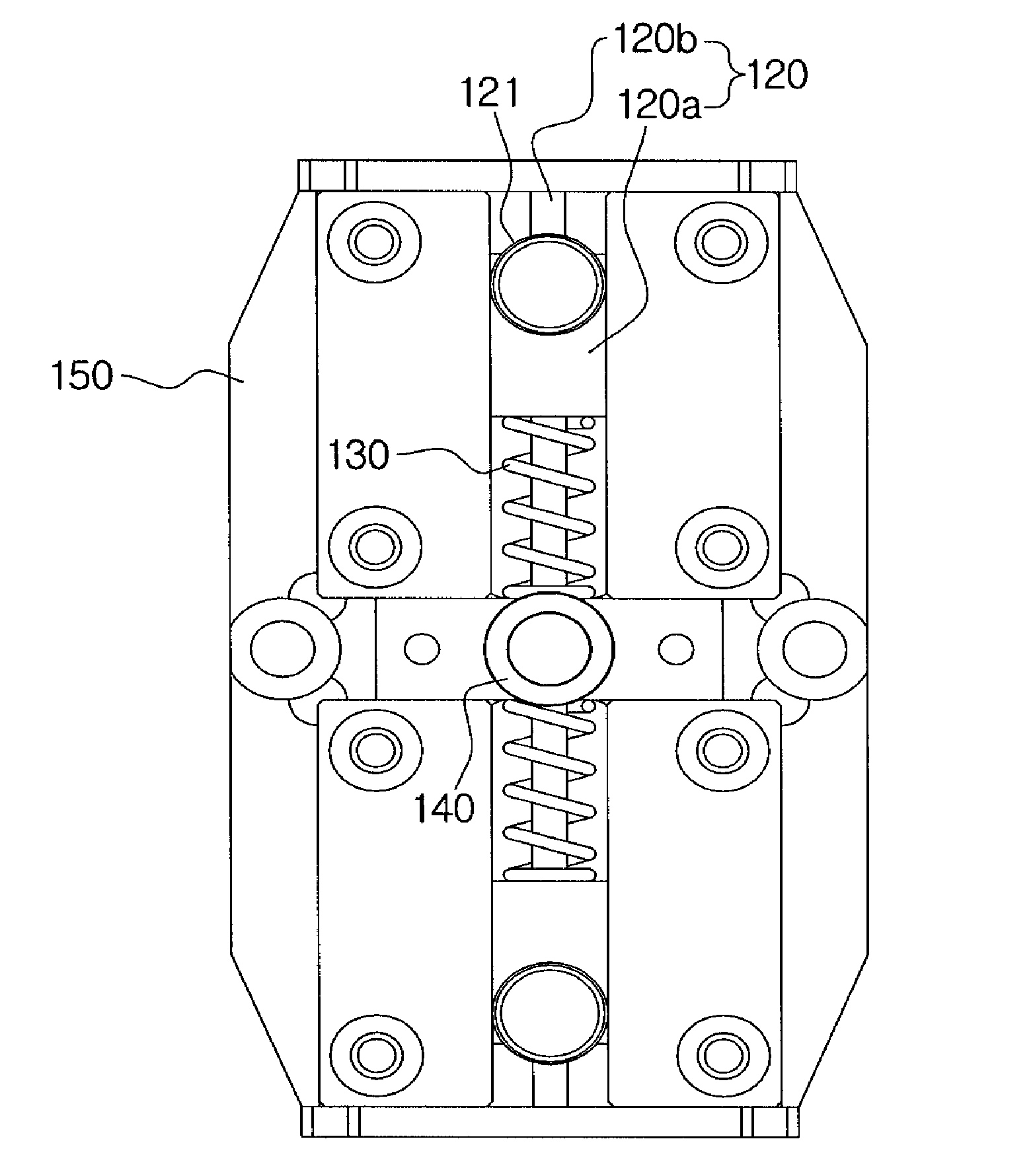
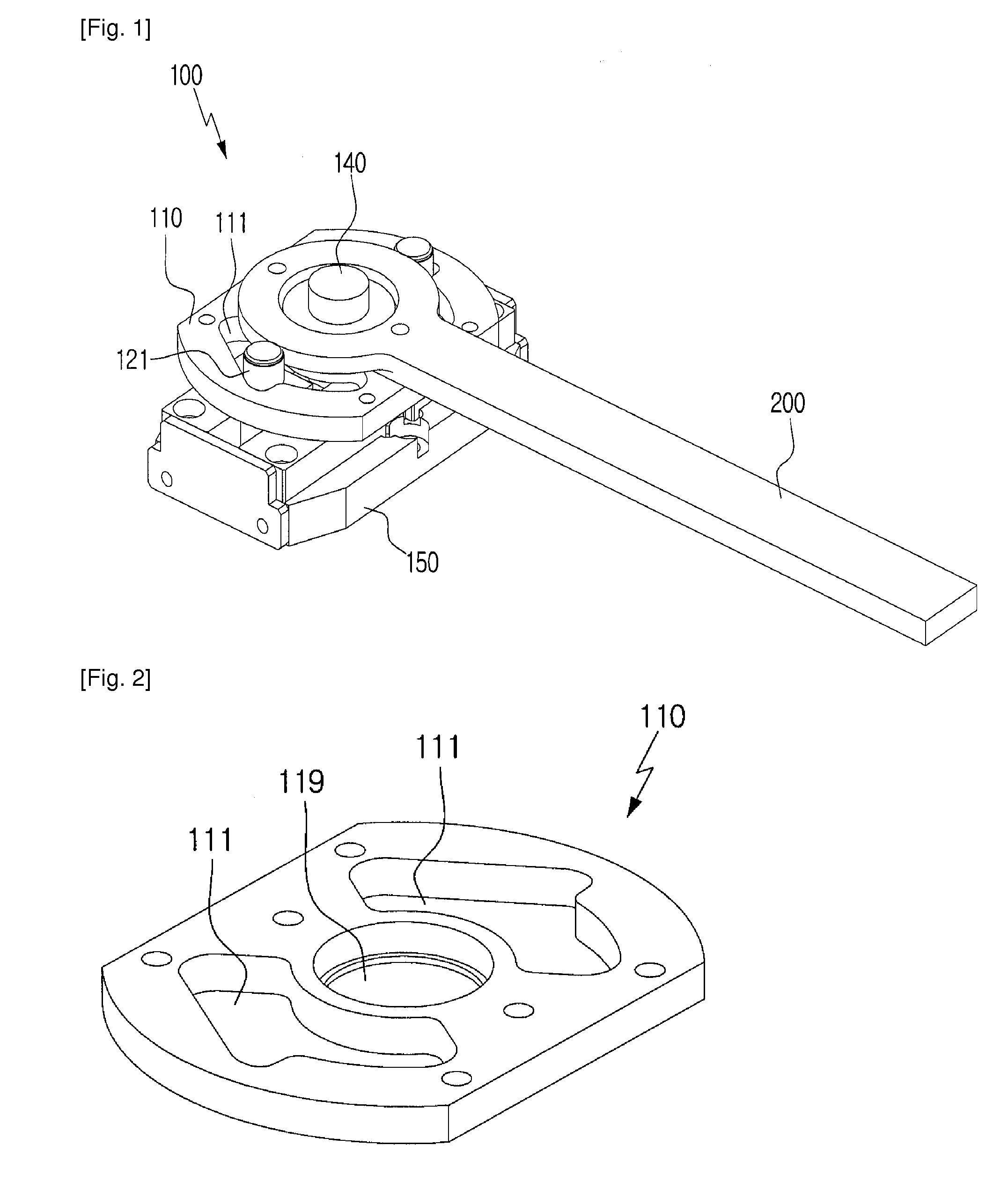
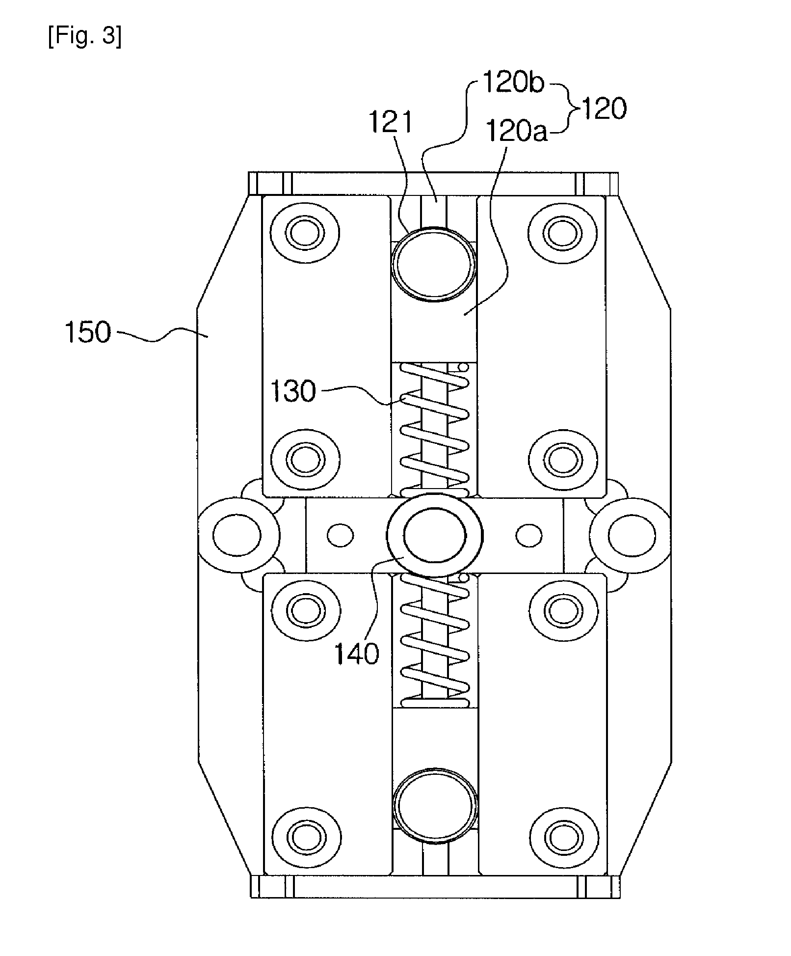
[0036]FIG. 1 is a perspective view of a limit torque generating device according to an embodiment of the invention, the limit torque generating device having a rotating member 200 connected thereto. FIG. 2 is a perspective view of a cam member 110 according to the embodiment of the invention. FIG. 3 is a plan view of the limit torque generating device according to the embodiment of the invention, the limit torque generating device including a flexible member 120 and an elastic member 130.

[0037]As shown in FIG. 1, the rotating member 200 is connected to the cam member 110. The rotating member 200 and the cam member 110 are coupled to each other through a fixing element such as a screw so as to be rotated together.

[003...


PUM


Abstract

The present invention relates to a device for generating limit torque, which generates a rotational displacement to protect a rotating device and automatically returns to the initial position when an external force is eliminated, and a rotating device using the same. The device includes a flexible member that is vertically connected to a rotating shaft and of which the length can be varied in an inward and outward direction with respect to the rotating shaft; an elastic member that is connected to the flexible member and causes the flexible member to receive an elastic force in the outward direction with respect to the rotating shaft; and a cam member that is rotatably connected to the rotating shaft and delivers a rotating force of the rotating shaft to a rotating member. The cam member has a through-hole in which a rotational displacement is generated and through which the flexible member returns to the initial position. According to the present invention, the device for generating limit torque can generate limit torque with a relatively simple structure, and can secure stability.

Description

TECHNICAL FIELD [0001]The present invention relates to a device for generating limit torque and a rotating device using the same, and more particularly to a device for generating limit torque, which generates a rotational displacement to protect a rotating device, when an external force equal to or greater than predetermined torque is applied to a rotating member of a rotating device such as a joint of a robot manipulator, and returns to the initial position when the external force is eliminated, and a rotating device using the same.BACKGROUND ART [0002]In general, a rotating device such as a joint of a robot manipulator includes a driving unit such as a driving motor, a rotating shaft which is connected to the driving unit so as to deliver a rotating force, and a rotating member which is connected to the rotating shaft so as to rotate.[0003]The rotating member is rotated about the rotating shaft by the rotating device, and a variety of operations are performed by the rotation of th...

Claims


Application Information

Patent Timeline
Patent Type & Authority Applications(United States)
IPC IPC(8): B25J19/06F16D7/00
CPCF16D7/10B25J19/06B25J9/1633F16D7/007
Inventor LEE, WOO SUBKANG, SUNG CHULKIM, MUN SANGCHOI, JUN HOCHUN, CHANG MOOK
Owner KOREA INST OF SCI & TECH
Why Eureka
Try Eureka