LED Modules for Sign Channel Letters and Driving Circuit

a technology of led modules and driving circuits, which is applied in the direction of identification means, display means, instruments, etc., can solve the problems that the embodiment cannot necessarily achieve any of these objectives, and achieve the effects of reducing the terminal voltage, easy installation, and easy removal and replacemen

Inactive Publication Date: 2011-04-14
PRINCIPAL LIGHTING GRP LLC
View PDF53 Cites 7 Cited by
  • Summary
  • Abstract
  • Description
  • Claims
  • Application Information

AI Technical Summary

Benefits of technology

[0008]An object of the present invention is to provide an LED lighting system for sign channel letters whereby LEDs are connected in series to avoid high current driving requirements.
[0009]An object of the present invention is to provide shunts in parallel with the LEDs so that the current path is maintained when an LED fails, so that the remaining LEDs not only provide their desired lighting function, but also so that the defective LED can be easily identified and replaced.
[0011]An object of the present invention is to provide an output signal for driving the LED light string which has a balanced output relative to ground to minimize the terminal voltage seen by the system relative to ground.
[0012]An object of the present invention is to provide overload protection to ensure that the user will not overload the system by running an excessive number of LED modules on one string.
[0013]An object of the present invention is to provide an LED module to enable easy installation of an LED in a circuit, and provide easy removal and replacement of a failed LED in the circuit.

Problems solved by technology

However, an embodiment need not necessarily achieve any of these objectives.

Method used


Image

  • LED Modules for Sign Channel Letters and Driving Circuit
  • LED Modules for Sign Channel Letters and Driving Circuit
  • LED Modules for Sign Channel Letters and Driving Circuit

Examples


Embodiment Construction

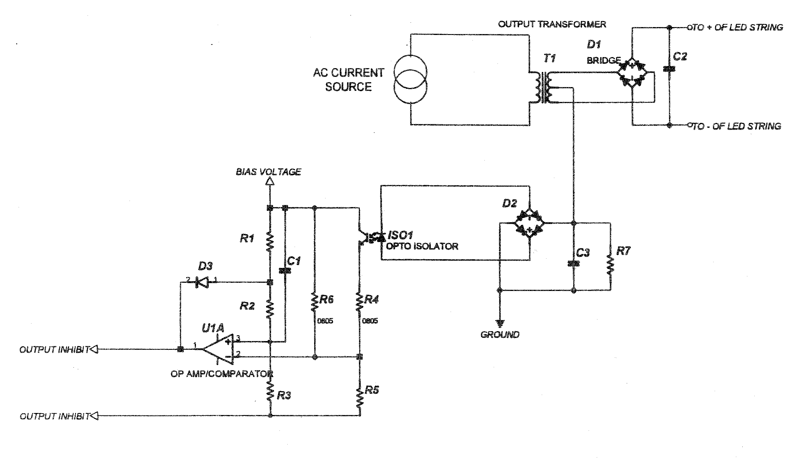
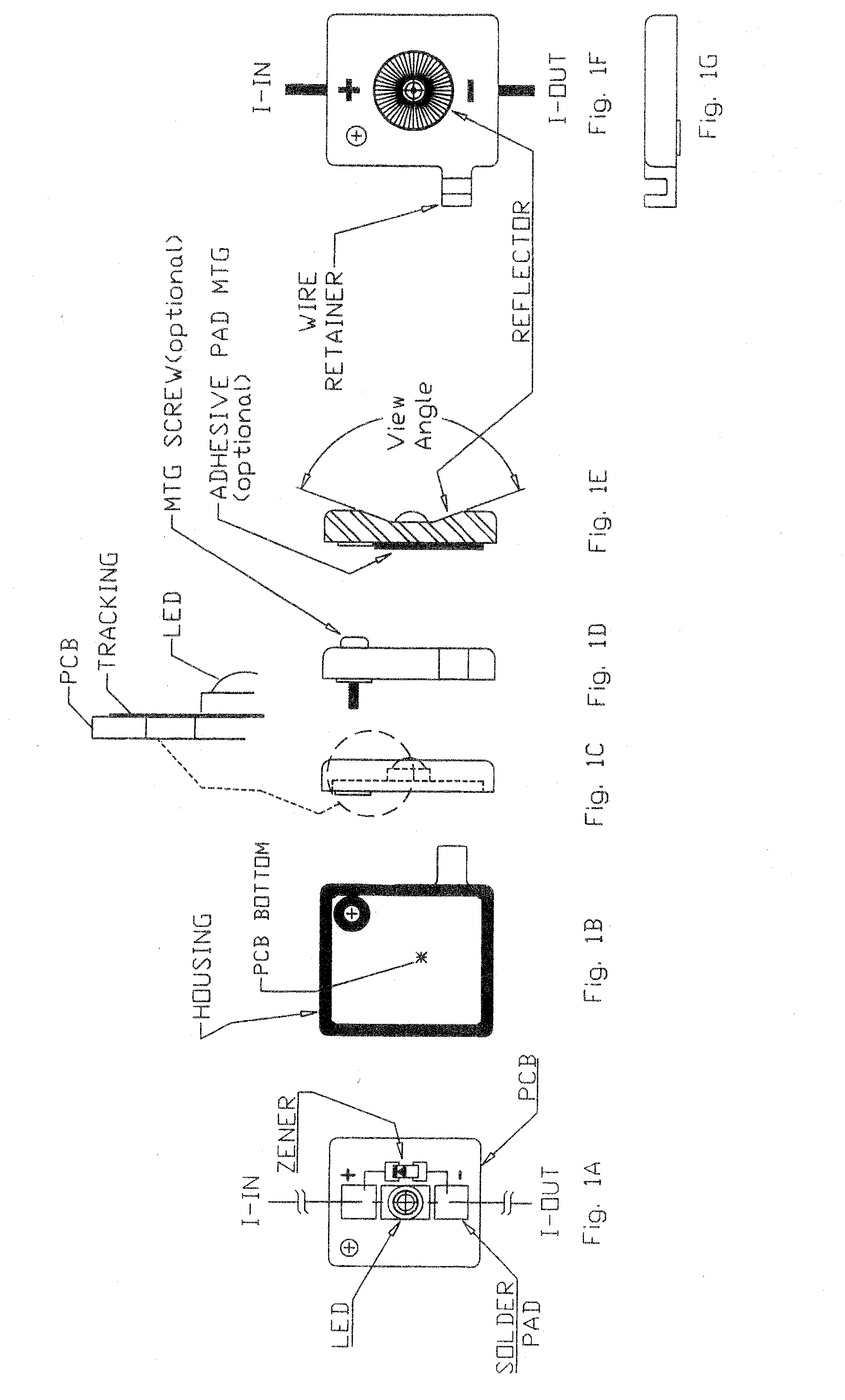
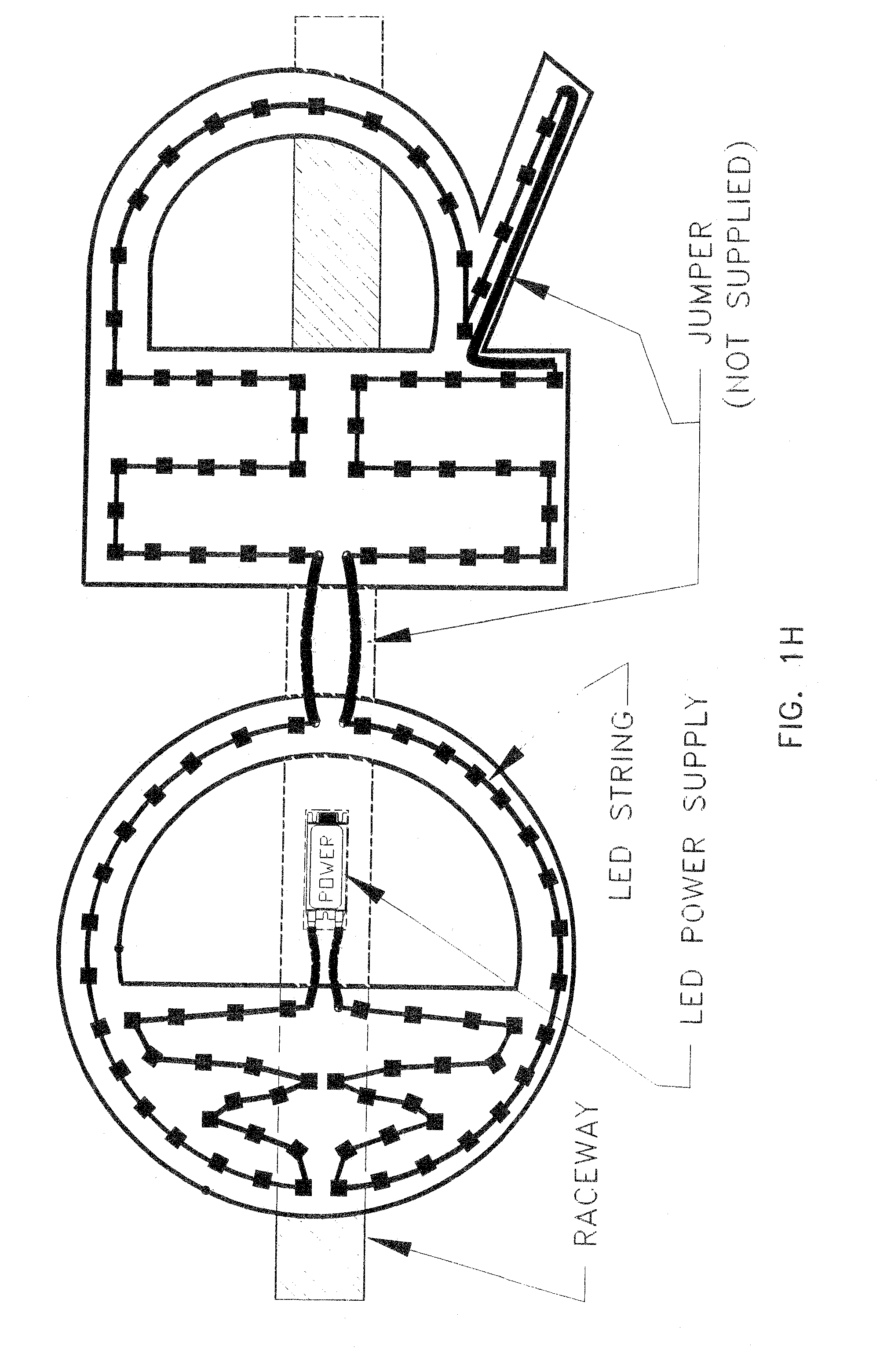
[0037]The invention provides an LED module for use in a lighting circuit for illumination of channel letters in a sign and having LED modules connected in series to a source of constant current, comprising a substrate, an electrical circuit mounted on the substrate, said electrical circuit consisting essentially of an LED and a shunt element connected in parallel with the LED, the electrical circuit having two electrical connection points for connecting the LED module to other modules in a series circuit.

[0038]The substrate may be mounted in a housing, and the module may further comprise a clip on the exterior of the housing for accepting and mounting a return power wire. The shunt element may be a Zener diode. The substrate may include a heat sink for dissipating heat. The substrate may include at least one mounting region at an edge for mounting the module. The mounting region may comprise at least one of a notch and a hole. The module may include an insulating cover. The insulati...


PUM


Abstract

An LED module for use in sign letter channel lights comprises a substrate, a reflector mounted on the substrate, an LED mounted within the reflector on the substrate and a Zener diode shunt element connected in parallel across the LED, a printed circuit board on the substrate, wherein the LED is mounted on the printed circuit board, and an insulating cover. The module may be entirely encapsulated. An LED driving protection circuit provides ground fault protection for a plurality of series connected LED modules.

Description

BACKGROUND OF THE INVENTION[0001]The present invention relates to light emitting diode (LED) light systems for channel letters in signs, particularly to LED systems serially connected with shunts for each LED, and circuits for driving the LEDs which provide circuit safety protection, and to provide an LED module for series connection with other LED modules.[0002]LEDs have become very popular for providing illumination in the sign industry due to their superior efficiency compared to incandescent and fluorescent bulbs, and the avoidance of harmful mercury in fluorescent bulbs. LEDs are also smaller and generally easier to ship, store and install than the prior light sources. Advancements in LED technology have also made LEDs even more desirable.[0003]LEDs have been used in parallel circuits in the sign industry, but a disadvantage is that increased current is required to drive them in parallel. Such systems typically use a low voltage, high current class 2 power supply.[0004]In the p...

Claims


Application Information

Patent Timeline
Patent Type & Authority Applications(United States)
IPC IPC(8): H02H3/00
CPCG09F13/22G09F9/33
Inventor PARKER, FRANCIS J.CRAWBUCK, ROBERTPADURARIU, EMILIAN
Owner PRINCIPAL LIGHTING GRP LLC
Why Eureka
Try Eureka