Bearing Wheels

a technology of bearing wheels and bearings, which is applied in the direction of skateboards, roller skates, sports apparatus, etc., can solve the problems of poor wheel performance and damage, loss of grease from bearings, and inconvenient tolerance across bearing diameters of conventional bearing wheels to promote longer life of bearings, so as to improve the resistance to heat conduction and expansion of the wheel centre, improve the air flow, and improve the effect of heat dissipation

Inactive Publication Date: 2011-06-30
NAMIS ENG
View PDF10 Cites 4 Cited by
  • Summary
  • Abstract
  • Description
  • Claims
  • Application Information

AI Technical Summary

Benefits of technology

[0014]It is an object of a first aspect of the present invention to provide bearing wheels that have air flow passageways through the wheel centre which improve air flow through the wheel centre for dissipating excess heat caused by friction when the wheels are being used.
[0015]It is an object of a second aspect of the present invention to provide bearing wheels that have improved resistance to heat conduction and expansion of the wheel centre caused by frictional heat generated during use.

Problems solved by technology

The bearing wheels used on skateboards often spin for long periods of time at high rotational velocity, and so are affected by heat caused by friction.
There is little or no effective air flow through the wheel centre for dissipating that heat, and so the bearings housed in the centre are subjected to intense heat that often causes at least some liquification of the bearing grease, resulting in the loss of that grease from the bearings and subsequent poor wheel performance and damage.
The tolerance across the bearing diameters in conventional bearing wheels is also not suitably tight to promote longer life of the bearings.
Poor tolerance is exacerbated by the heat conduction and expansion that the wheel centre experiences as a result of frictional heat generated at the outer surface of the wheel.
There have been various attempts in the prior art to address these problems, but most of them have proved unsuccessful functionally or structurally.

Method used


Image

  • Bearing Wheels
  • Bearing Wheels
  • Bearing Wheels

Examples


first embodiment

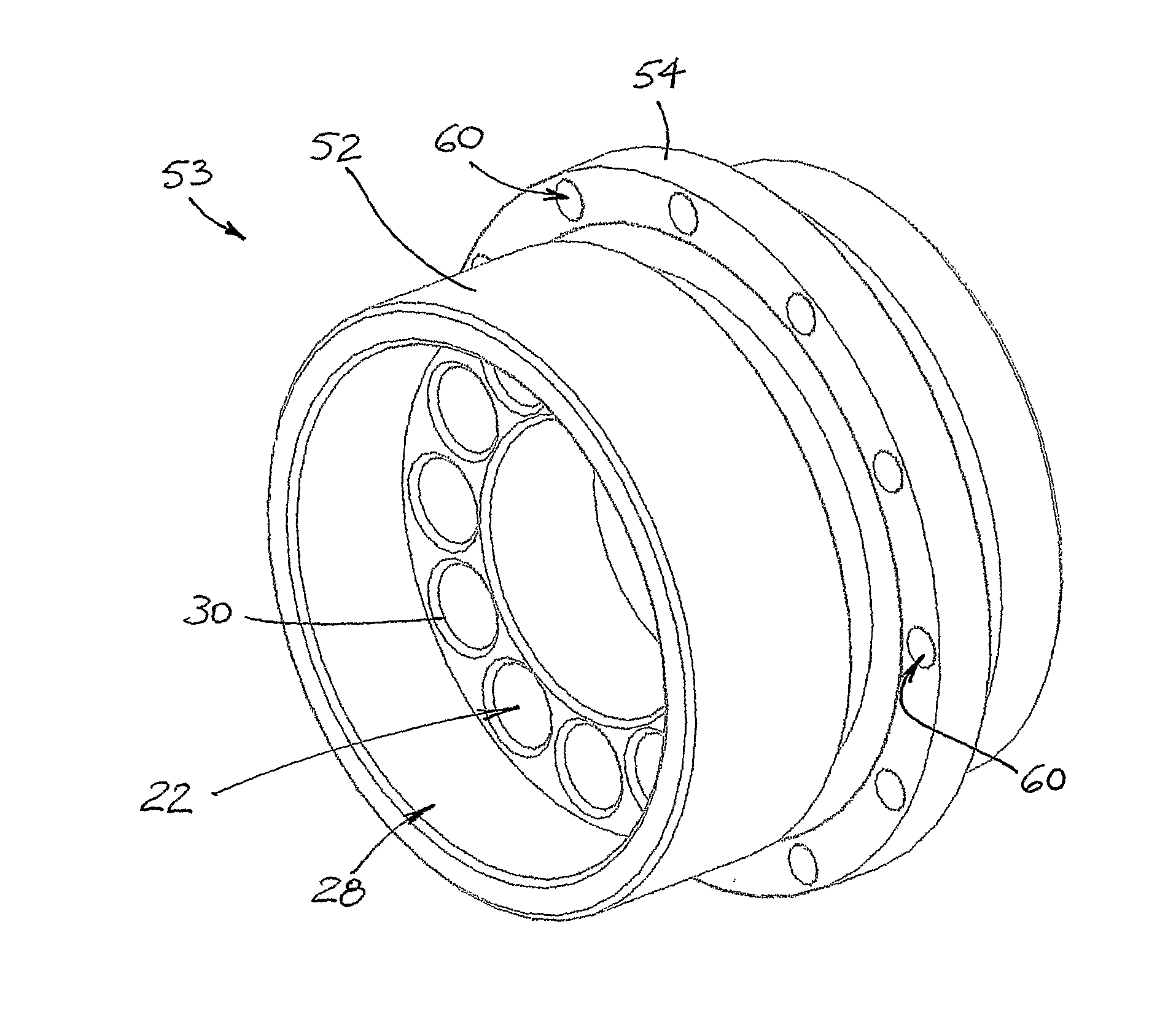
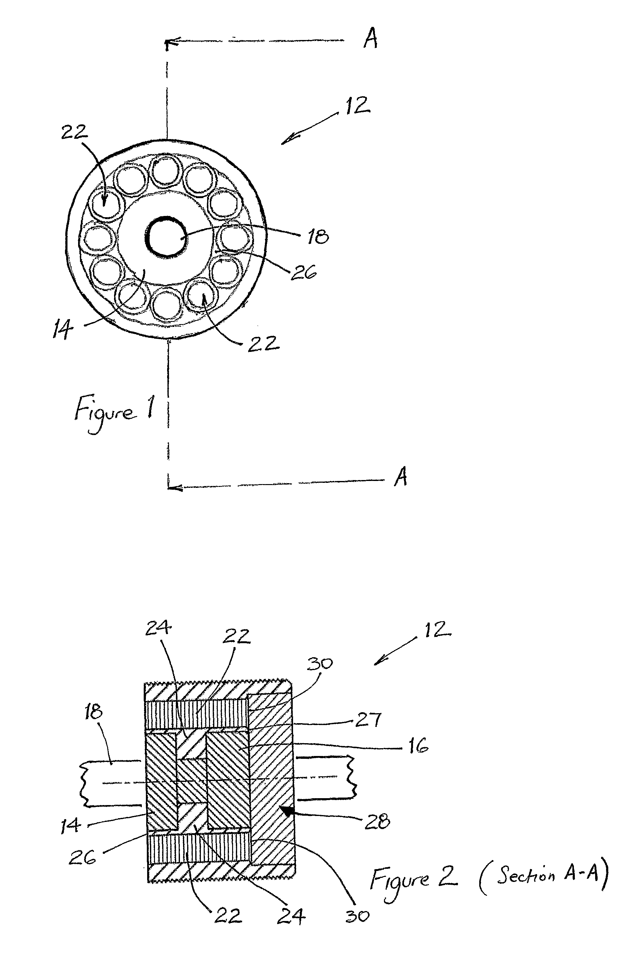
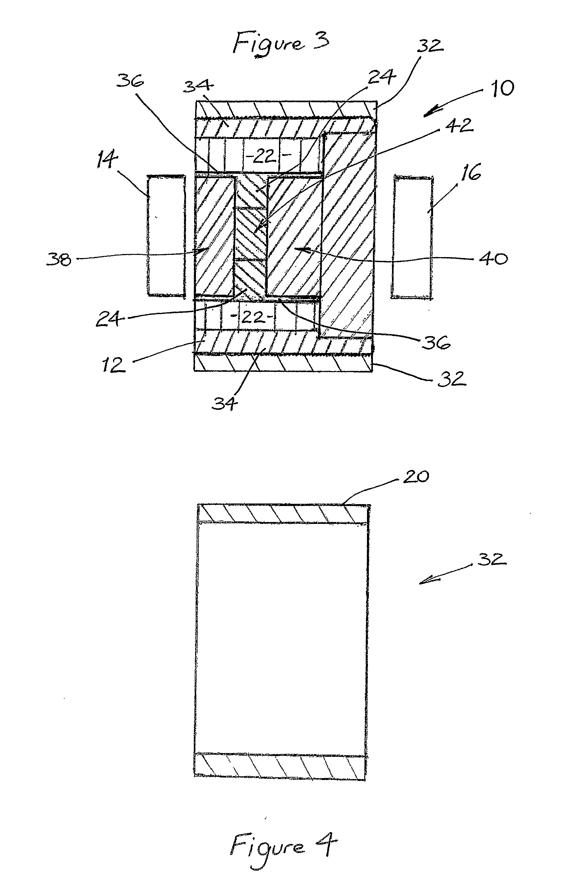
[0054]With reference now to a bearing wheel according to the invention shown in FIGS. 1 to 4, the bearing wheel 10 includes a wheel centre 12, a pair of bearings 14, 16 housed in the wheel centre and adapted to allow the wheel centre to spin about an axle 18 around which the bearings are mounted. The bearing wheel 10 also includes an outer surface 20 for contacting a frictional surface, such as the ground, over which the wheel centre is to roll. There are also air flow passageways 22 formed through the wheel centre. The air flow passageways extend between opposite sides of the wheel centre to allow air flow therethrough to dissipate excess heat caused by friction while the wheel is moving on the frictional surface.

[0055]The wheel centre 12 has a main body portion 24 that is offset to one side of the wheel 10 so that one side 26 of the main body portion is substantially in the plane of one side of the outer surface and the other side 27 of the main body portion is recessed from the p...

second embodiment

[0065]With reference now to a bearing wheel according to the invention shown in FIGS. 5 to 8, the bearing wheel 50 is similar to the bearing wheel 10 except in the way that the cap is secured upon the outer portion of the wheel centre. For ease of reference, like features have been given like numerals. Reference should be made to the above description of the bearing wheel 10 for an understanding of the structure and function of the like features in the bearing wheel 50.

[0066]The outer portion 52 of the wheel centre 53 has a projecting annular rib 54 surrounded on both sides by circumferential grooves 56, 58. The rib 54 has a plurality of equally spaced apart holes 60 drilled across it. The surface profile of the outer portion 52 allows the cap 62 to be secured upon it in an improved way. When, say, molten polyurethane is poured into the mould that forms the cap upon the wheel centre during manufacture, the polyurethane flows into the grooves 56, 58 and through the holes 60 to form a...

third embodiment

[0067]With reference now to a bearing wheel according to the invention shown in FIGS. 9 to 12, the bearing wheel 70 is similar to the bearing wheels 10 and 50 except that it lacks a stepped recess in one side of the wheel centre, and in the way that the cap is secured upon the outer portion of the wheel centre. For ease of reference, like features have been given like numerals. Reference should be made to the above description of the bearing wheels 10 and 50 for an understanding of the structure and function of the like features in the bearing wheel 70.

[0068]The bearing wheel 70 is manufactured to be of smaller width and diameter than the bearing wheels 10 and 50. The bearing wheel 70 lacks a stepped recess in one side of the wheel centre 72. The wheel centre 72 has a main body portion 74 that is symmetrical, and both sides of the main body portion 74 are outermost and present a respective face at which there are openings 76 to respective passageways 77.

[0069]Despite the absence of ...


PUM


Abstract

A bearing wheel (50) has a wheel centre (53) and bearings (14, 16) housed in the wheel centre which are adapted to allow the wheel centre to spin about an axle (18) around which the bearings are mounted. There is an outer surface (20) for contacting a frictional surface over which the wheel centre is to spin. Air flow passageways (22) are formed through the wheel centre, and extend between opposite sides of the wheel centre to allow air flow therethrough to dissipate excess heat caused by friction while the wheel is moving on the frictional surface.

Description

FIELD OF THE INVENTION[0001]The present invention relates to improved bearing wheels and, in particular, to bearing wheels that are used on skateboards, roller skates and the like.[0002]In one aspect, the present invention relates to bearing wheels that have improved air flow through the wheel centre for dissipating excess heat caused by friction when the wheels are being used.[0003]In another aspect, the present invention relates to bearing wheels that have improved resistance to heat conduction and expansion of the wheel centre caused by frictional heat generated during use.[0004]Although the background, objects and preferred embodiments of the invention will be hereinafter described with reference to a bearing wheel for use on skateboards, it is to be understood that the invention is not limited thereto but has wider application. For example, the bearing wheels may be used on roller skates and other movable devices, as well as on stationary devices, such as machinery in which bea...

Claims


Application Information

Patent Timeline
Patent Type & Authority Applications(United States)
IPC IPC(8): A63C17/22
CPCA63C17/223B60B27/02B60B37/10B60B19/10B60B19/08F16C2316/30
Inventor ELOVARIS, PETER
Owner NAMIS ENG
Why Eureka
Try Eureka