Development device and image forming apparatus including the same

a development device and image forming technology, applied in electrographic process apparatus, instruments, optics, etc., can solve the problems of reducing the density of the image printed on a recording medium, the extreme degradation of the fluidity of the developer, and the reduction of the density of the developer fluidity. , to achieve the effect of reducing the stress and reducing the degradation of the developer fluidity

Active Publication Date: 2011-12-15
SHARP KK
View PDF1 Cites 0 Cited by
  • Summary
  • Abstract
  • Description
  • Claims
  • Application Information

AI Technical Summary

Benefits of technology

[0020]According to the development device of the present invention, for example, when the developer raking member is provided in the first communication path, the developer conveyed onto the downstream side of the first developer conveyance path is raked and delivered to the second developer conveyance path by the developer raking member, which allows the retention of the developer in a downstream end part of the first developer conveyance path. Therefore, the pressure applied to the developer conveyed to the lowermost downstream side of the first developer conveyance path can be relaxed to reduce the stress. The pressure applied to the developer is generated by pressing the developer against a downstream inside wall surface of the developer tank. The same holds true for the case in which the developer raking member is provided in the second communication path.
[0021]Additionally, because a circumferential rotation blade is provided on the conveyance direction downstream side of the first and second developer conveying members, a circumferential conveyance power (agitation power in rotation direction) by the circumferential rotation blade is transmitted to the developer conveyed onto the conveyance direction downstream side by the spiral blades in the first and second developer conveyance paths. Therefore, the developer is hardly pressed against the downstream inside wall surfaces of the first and second developer conveyance paths, and the developer is hardly retained in the corners of the downstream end parts of the first and second developer conveyance paths. As a result, on the downstream sides of the first and second developer conveyance paths, the developer can smoothly be moved onto the sides of the first and second communication paths without retaining the developer while the degradation of the developer fluidity is reduced.

Problems solved by technology

However, there is a problem in the development device of Japanese Patent Application Laid-Open No. 4-240677.
When such stress as the compressive force continues over a long period, a fluidity improver that is of a toner additive is buried in resin particles constituting the toner, which results in a phenomenon in which developer fluidity is extremely degraded to hardly convey the developer.
As a result, a sufficient amount of the developer is hardly supplied to the photoconductive drum through the development roller, which results in a problem in that density of the image printed on a recording medium is reduced.

Method used


Image

  • Development device and image forming apparatus including the same
  • Development device and image forming apparatus including the same
  • Development device and image forming apparatus including the same

Examples


first embodiment

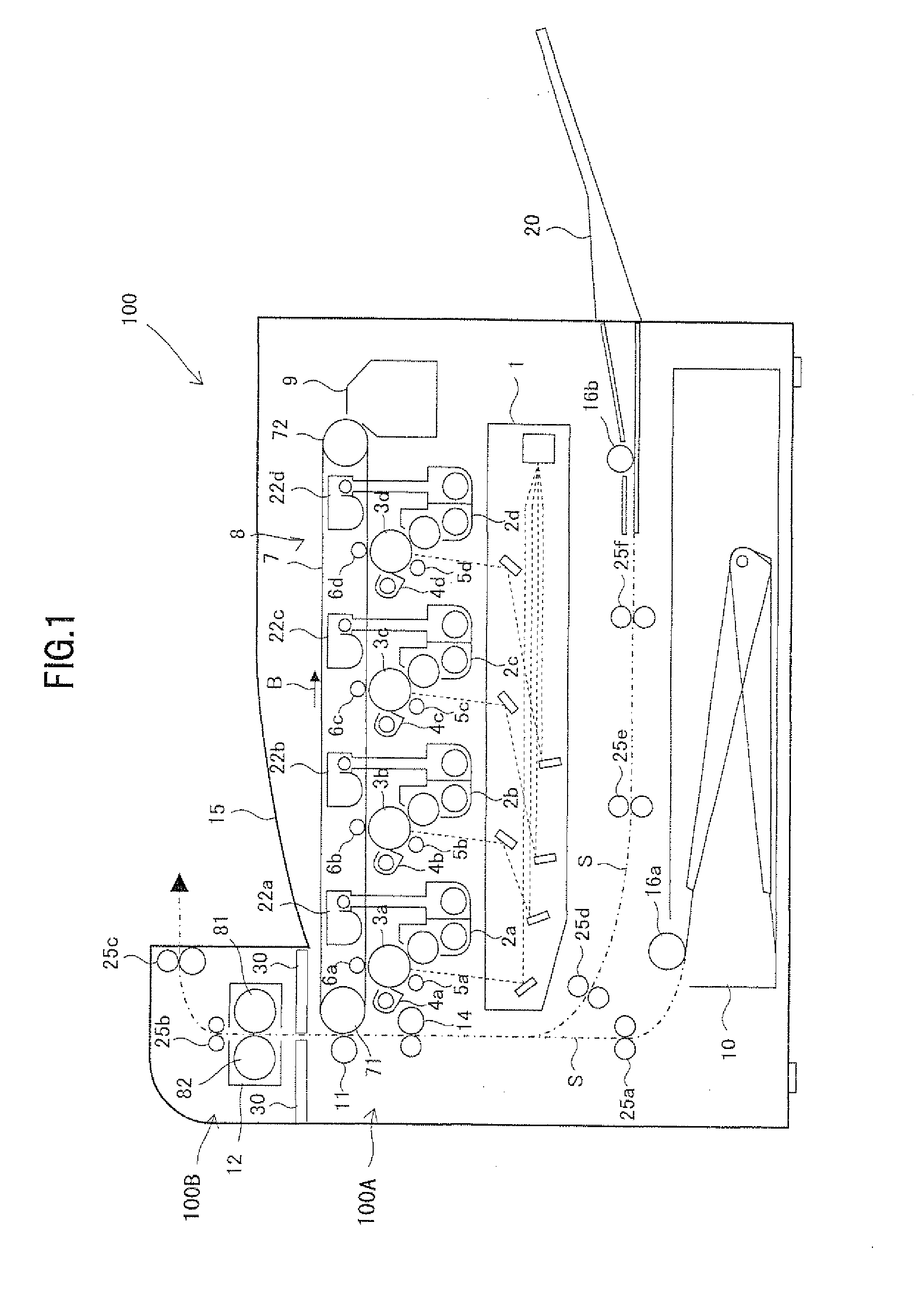
[0046]FIG. 1 illustrates an entire configuration of the image forming apparatus including the development device according to a first embodiment of the present invention. An image forming apparatus 100 including a development device accommodation portion 100A in which plural development devices 2a to 2d are accommodated in a casing, a fixing device accommodation portion 100E in which a fixing device 12 is accommodated above the development device accommodation portion 100A in the casing, and a division wall 30 that is provided between the development device accommodation portion 100A and the fixing device accommodation portion 100B to insulate heat of the fixing device 12 such that the heat is not transferred onto a development device side. For example, the image forming apparatus 100 is a printer that can form a multi-color or monochrome image on a sheet-like recording medium (recording sheet) according to externally-transmitted image data. An upper surface of the development devic...


PUM


Abstract

A development device comprising a developer conveying member and a developer raking member that are rotatably disposed in the developer conveyance path to conveying and agitating the developer in the developer conveyance paths, wherein the developer conveyance path includes first and second developer conveyance paths and first and second communication paths that communicating the first and second developer conveyance paths on both sides, the developer conveying member includes first and second developer conveying members that are disposed in the first and second developer conveyance paths, the developer raking member is disposed in at least one of the first and second communication paths.

Description

CROSS-REFERENCE TO RELATED APPLICATION[0001]This application is related to Japanese patent application No. 2010-135146 filed on Jun. 14, 2010 whose priority is claimed under 35 USC §119, the disclosure of which is incorporated by reference in its entirety.BACKGROUND OF THE INVENTION[0002]1. Field of the Invention[0003]The present invention relates to a development device in which a two-component developer is used and an image forming apparatus including the same.[0004]2. Description of the Related Art[0005]Recently a two-component developer (hereinafter simply referred to as “developer”) having excellent toner charging stability is widely used in an electrophotographic image forming apparatus that meets a full-color image and a high-quality image. The developer includes a toner and a carrier. When the developer is agitated in a developer tank of a development device, a properly-charged toner is obtained by friction between the toner and the carrier. In the development device, the ch...

Claims


Application Information

Patent Timeline
Patent Type & Authority Applications(United States)
IPC IPC(8): G03G15/08
CPCG03G15/0889G03G15/0893G03G2215/085G03G2215/0827G03G2215/0838G03G2215/0822
Inventor MIHARA, KOICHINAGAI, TAKAFUMI
Owner SHARP KK
Why Eureka
Try Eureka