Fan diversion sturcture

Inactive Publication Date: 2012-05-17
LIN CHEN CHANG
View PDF8 Cites 2 Cited by
  • Summary
  • Abstract
  • Description
  • Claims
  • Application Information

AI Technical Summary

Benefits of technology

[0006]A primary object of the present invention is to provide a diversion structure that can eff

Problems solved by technology

An airflow direction mainly follows an axial direction of the fan, but convection efficiency around two sides of the fan is lower wherein the heat fails to be diffused efficiently.
Furthermore, the upright fan and ceiling fan are limited to a blowing angle range which is pre-set befo

Method used


Image

  • Fan diversion sturcture
  • Fan diversion sturcture
  • Fan diversion sturcture

Examples


Example

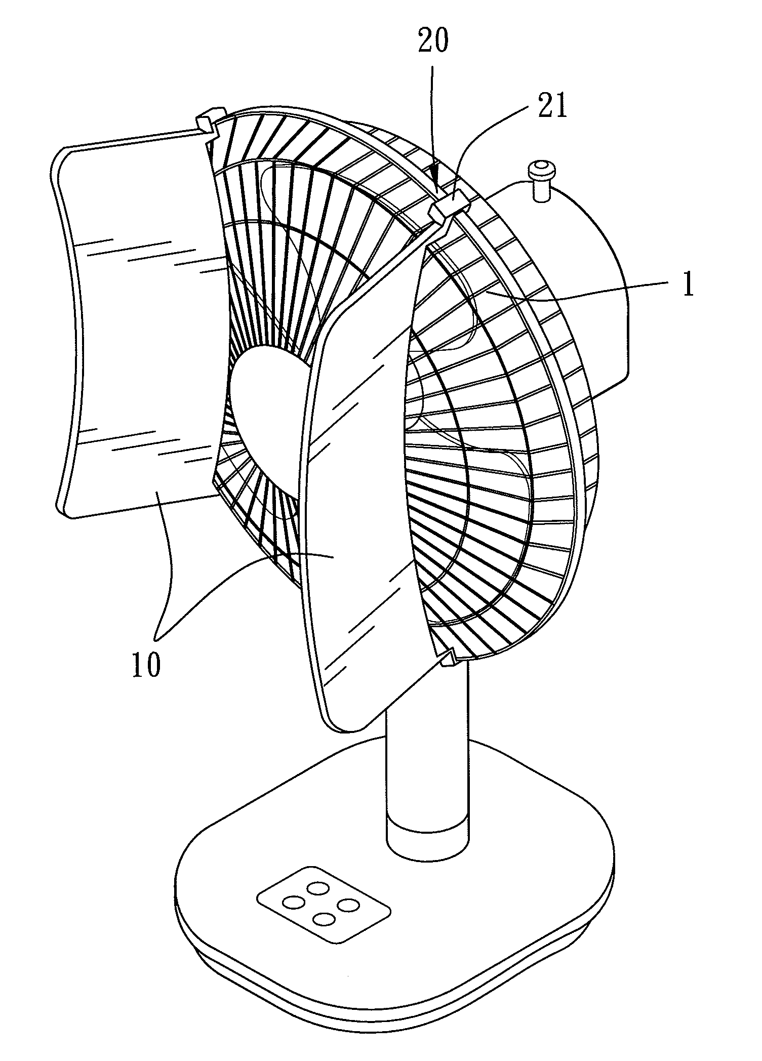
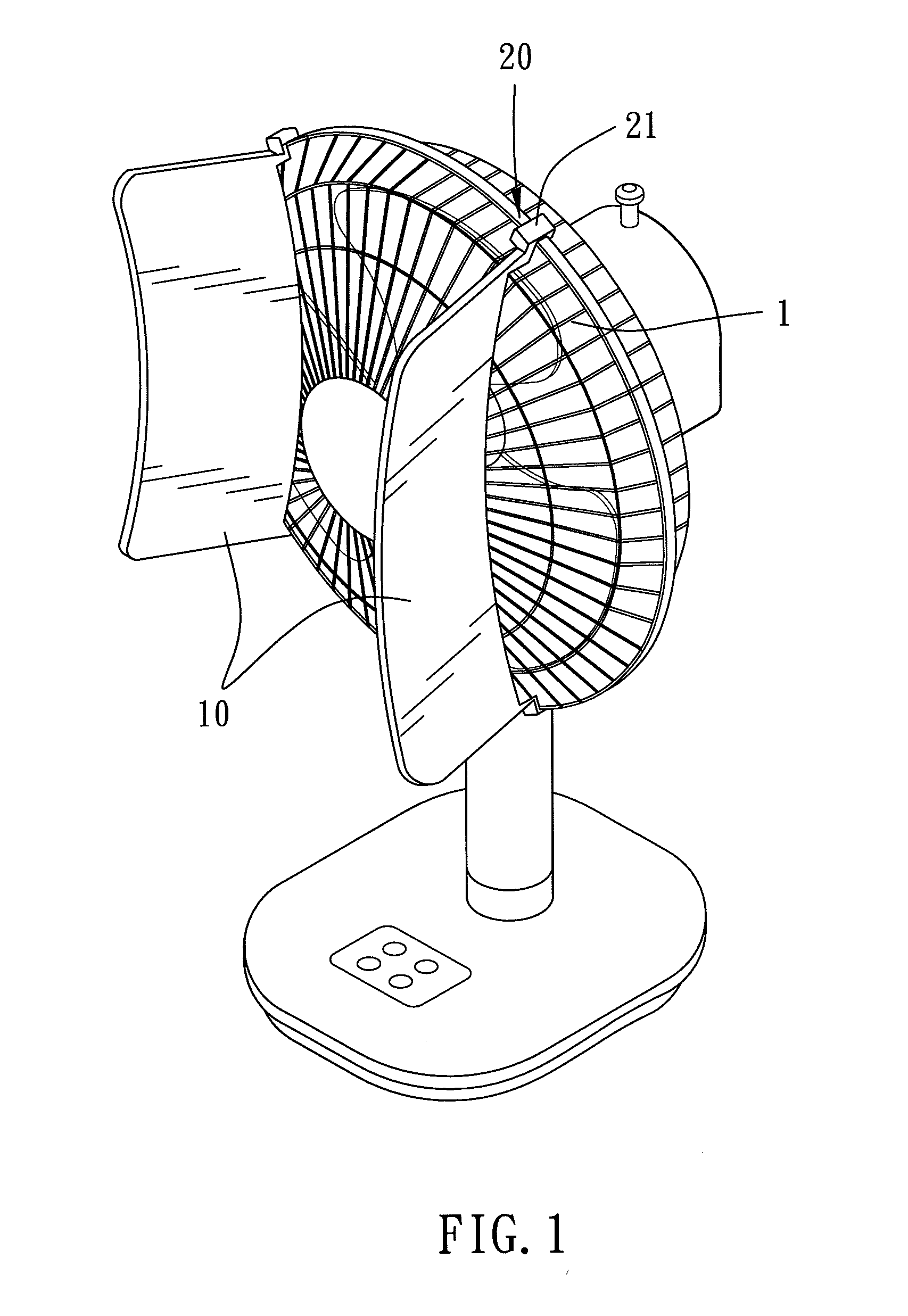
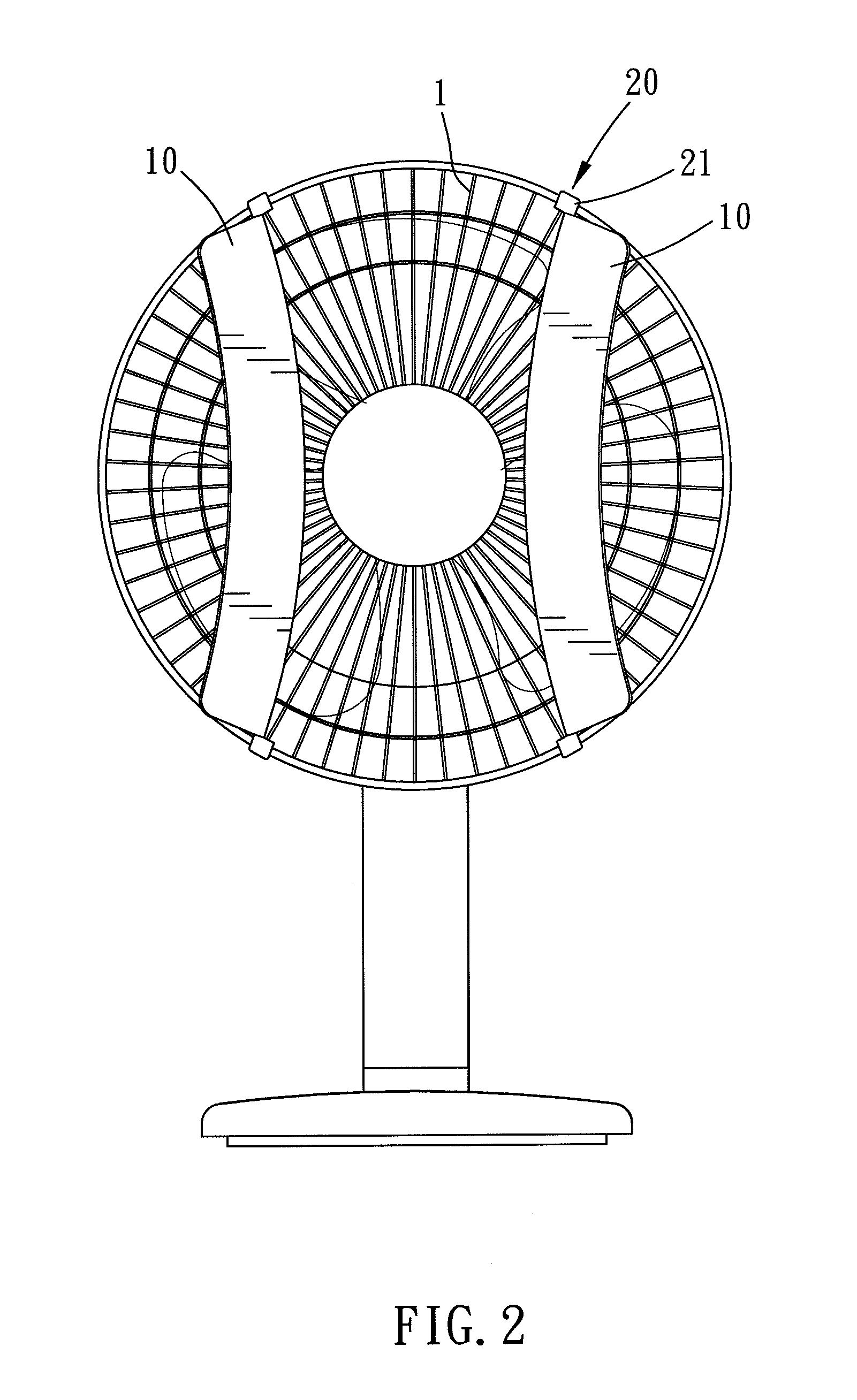
[0015]Please refer to FIGS. 1 and 2. In a preferred embodiment of the present invention, the fan diversion structure is used in combination with a fan. The definition of the fan includes an upright fan and a ceiling fan. This embodiment is combined with an upright fan for the following structure description.

[0016]The fan diversion structure of this invention comprises at least one deflector 10 and at least one connecting part 20. More specifically, the quantity of the deflectors 10 is two, and the quantity of the connecting parts 20 is two as well. The deflector 10, which is adapted to be disposed across front of an air outlet, is disposed on one side next to a center of the fan and without overlapping the center of the fan. Thereby, the deflector 10 avoids completely blocking an axial airflow from the fan, wherein the deflector 10 mainly extends aslant and outwardly so as to deflect the airflow to the side of the fan. Perfectly, the deflector 10 has a curved surface. The curved sur...


PUM


Abstract

The present invention is to offer a fan diversion structure which is adapted to be disposed on a fan, and the fan diversion structure comprises at least one deflector and at least one connecting part. The deflector, which is adapted to be disposed across front of an air outlet of the fan, is disposed on one side next to a center of the fan and without overlapping the center of the fan, wherein the deflector extends outwardly so as to deflect an airflow to the side direction of the fan. The connecting part is adapted for connecting the deflector to the fan. Thereby the airflow from the fan not only converges in the axial direction, but also moderately extends to the side of the fan so as to increase the blowing angle and enhance convection efficiency around the fan.

Description

BACKGROUND OF THE INVENTION[0001]1. Field of the Invention[0002]The present invention relates to a fan diversion structure, and more specifically to a structure for deflecting an airflow to one side of a fan.[0003]2. Description of the Prior Art[0004]A conventional fan such as an upright fan or a ceiling fan makes air flow forcibly with spin of its plural blades. An airflow direction mainly follows an axial direction of the fan, but convection efficiency around two sides of the fan is lower wherein the heat fails to be diffused efficiently. Furthermore, the upright fan and ceiling fan are limited to a blowing angle range which is pre-set before delivery from a factory. Consequently, the range of the cold airflow can reach is quite restricted. Therefore people sitting at the corner of an interior space often need to bear the muggy environment, and that's a common disadvantage of a conventional fan or ceiling fan structure.[0005]The present invention is, therefore, arisen to obviate o...

Claims


Application Information

Patent Timeline
IPC IPC(8): F24F13/08
CPCF04D29/544F04D29/541F24F13/08F04D29/703F24F7/007F04D29/701
Inventor LIN, CHEN-CHANG
Owner LIN CHEN CHANG
Why Eureka
Try Eureka