Method and system providing improved data matching for virtual planning

a virtual planning and data matching technology, applied in the field of craniofacial treatment, can solve the problems of misalignment of products produced based on matched data from the first set of data and the second set of data, and achieve the effects of improving the conformity of matched data, improving precision, and more precise manufacturing data

Active Publication Date: 2012-05-17
NOBEL BIOCARE SERVICES AG
View PDF14 Cites 29 Cited by
  • Summary
  • Abstract
  • Description
  • Claims
  • Application Information

AI Technical Summary

Benefits of technology

[0021]Some embodiments provide for a more precise matching of a first set of data and a second data set, providing a more precisely matched data set.
[0022]Some embodiments provide for more precise manufacturing data based on the matched data set, and thus products manufactured based on this manufacturing have higher precision.
[0023]Some embodiments provide an improved conformity of matched data to the anatomical craniofacial situation.
[0024]Some embodiments provide for introduction of fewer errors in a dental planning and production system.
[0025]Some embodiments provide for less sources of error in a chain of production of a dental planning and production system.
[0026]Some embodiments provide for final products that conform to the real anatomical craniofacial situation with high precision. Some embodiments thus provide for production of products to be used in dental restorative procedures with improved fit.

Problems solved by technology

When matching data elements from input sources having different spatial resolution, misalignment of products that are produced based on matched data from the first set of data and the second set of data may occur, e.g., due to interpolation errors when identifying the fiducial markers for matching.
The system and methods disclosed U.S. Pat. No. 6,947,038 are subject to the same issues as WO 2008 / 083857, due to the fact that 3D objects reconstructed from the different maps can have different resolutions, which lead to matching misalignments.

Method used


Image

  • Method and system providing improved data matching for virtual planning
  • Method and system providing improved data matching for virtual planning
  • Method and system providing improved data matching for virtual planning

Examples


Embodiment Construction

[0040]Specific embodiments of the inventions will now be described with reference to the accompanying drawings. These inventions may, however, be embodied in many different forms and should not be construed as limited to the embodiments set forth herein; rather, these embodiments are provided so that this disclosure will be thorough and complete, and will fully convey the scope of the inventions to those skilled in the art. The terminology used in the detailed description of the embodiments illustrated in the accompanying drawings is not intended to be limiting of the inventions. In the drawings, like numbers refer to like elements.

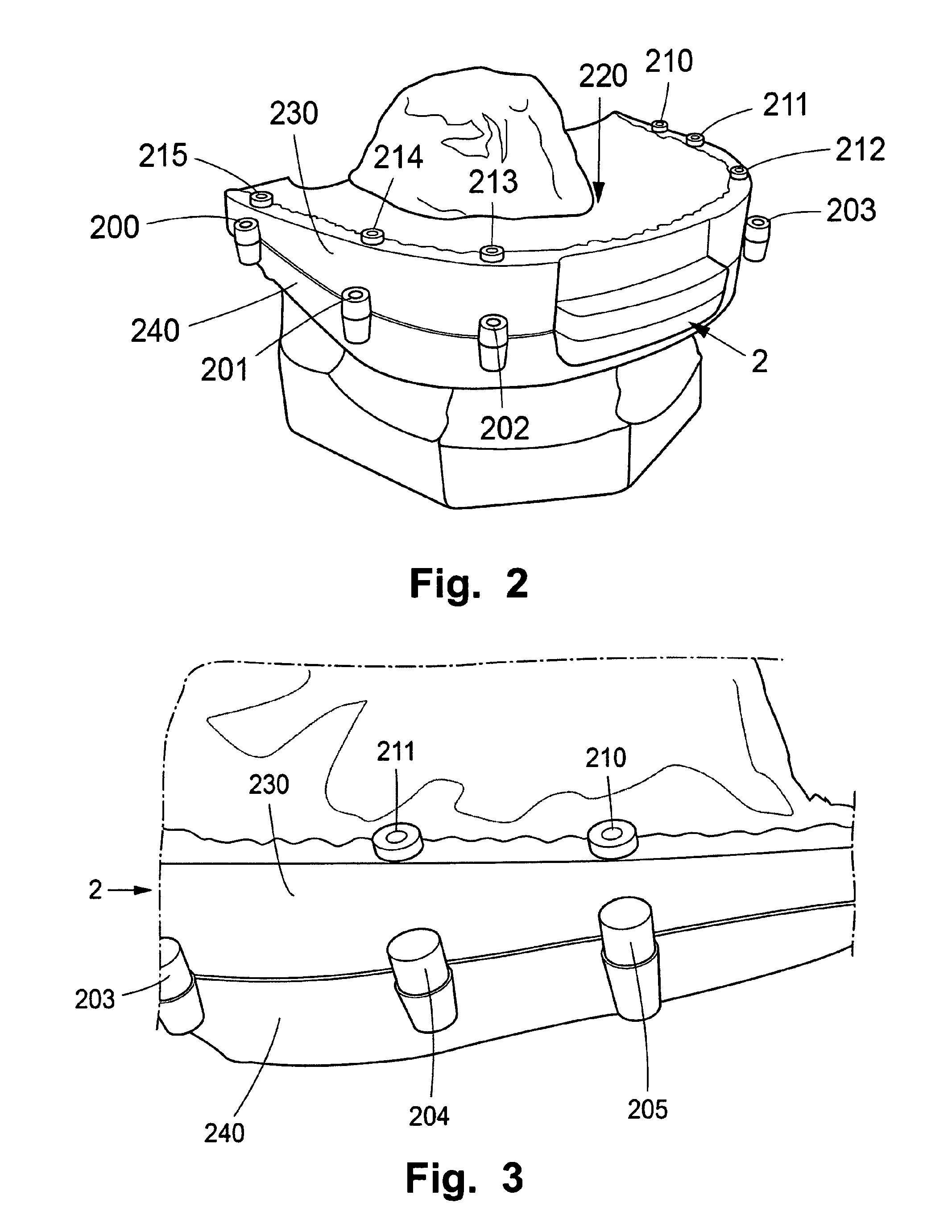
[0041]The following description focuses on certain embodiments applicable to a drill guided dental restorative procedure. However, it will be appreciated that the embodiments are not limited to this application but may be applied to many other dental restorative procedures, including for example bone shaping by means of surgical templates, positioning of ...


PUM


Abstract

A scanning structure having at least one surface with a shape adapted to conform to a portion of a craniofacial space is described. The scanning structure includes at least one surface object, which is at least partly identifiable from a first set of data, and where a first coordinate is identifiable based on the surface object. The scanning structure includes at least one volume object, which is at least partly identifiable from a second set of data, and where a second coordinate is identifiable based on the volume object. The surface object can be arranged in relation to the at least one volume object such that the first coordinate and the second coordinate have a pre-defined relationship to each other.

Description

CROSS-REFERENCE TO RELATED APPLICATIONS[0001]This application is a national stage application under 35 U.S.C. §371 of PCT Application No. PCT / EP2010 / 002998, filed on May 17, 2010, which published in English as WO 2010 / 133326 A2 on Nov. 25, 2010 and which claims priority benefit of European Patent Application No. 09006665.5, filed on May 18, 2009, the entire contents of which applications and publication are herein incorporated by reference in their entirety.BACKGROUND[0002]1. Field of the Invention[0003]This invention pertains in general to the field of craniofacial treatments. More particularly, the application relates to a method and system of matching of a first set of data and a second set of data related to a region of interest in a craniofacial space.[0004]2. Description of the Related Art[0005]In WO 2008 / 083857 A1 of the same applicant as the present application, which hereby is incorporated in its entirety by reference for all purposes, a method and system for planning a den...

Claims


Application Information

Patent Timeline
Patent Type & Authority Applications(United States)
IPC IPC(8): G06F19/00
CPCA61C1/084G06F19/3437G16H50/50A61C7/002A61C9/004
Inventor PETTERSSON, ANDREASNILSSON, URBAN
Owner NOBEL BIOCARE SERVICES AG
Why Eureka
Try Eureka