

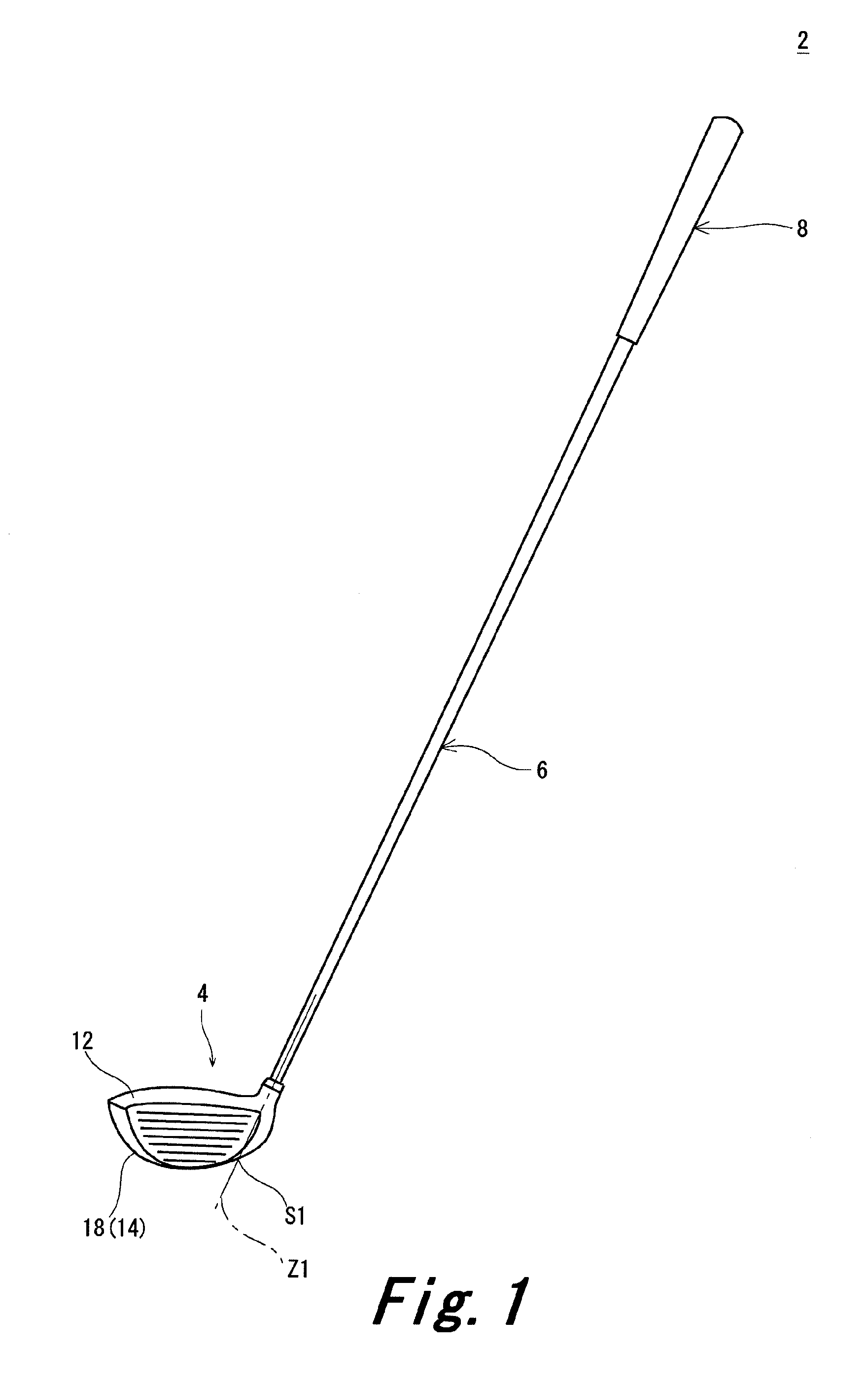
Golf club head and golf club
a golf club and head technology, applied in golf clubs, golf, sport apparatus, etc., can solve the problems of complicated sole shape, hole may complicate the sole shape, and complicated sole shape, etc., and achieve good head stability at the address and high degree of freedom in design of the sol
- Summary
- Abstract
- Description
- Claims
- Application Information
AI Technical Summary
Benefits of technology
Problems solved by technology
Method used
Image

Examples
example 1
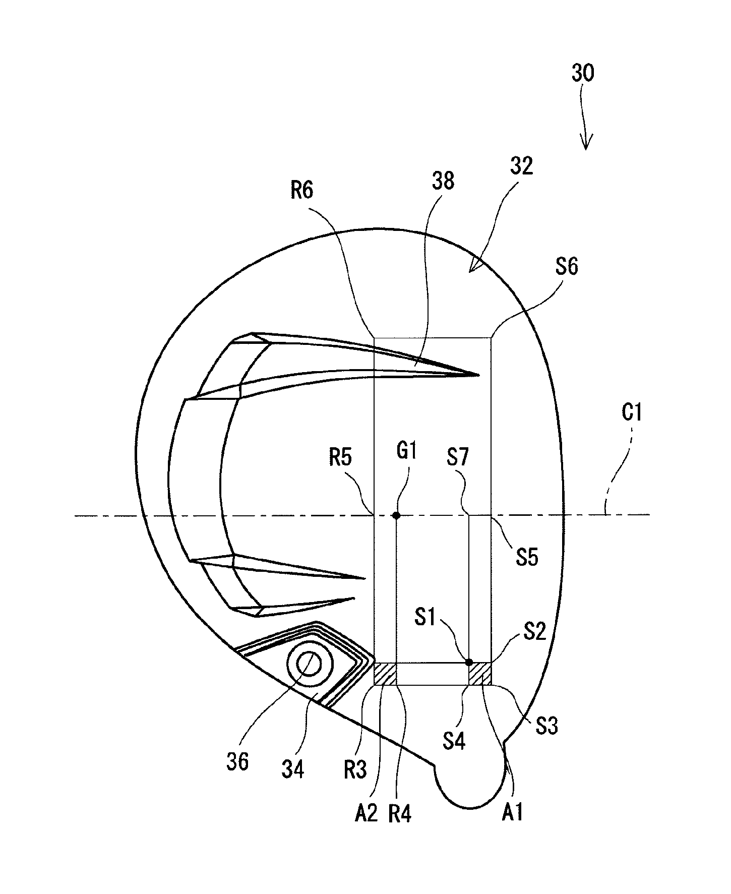
[0133]A head body and a face member were welded to obtain a wood type head shown in FIG. 8. The material of the head body was Ti-6Al-4V. A method for manufacturing the head body was a lost-wax precision casting. The material of the face member was Ti-6Al-4V. The face member was obtained by subjecting a rolling plate of Ti-6A1-4V to press processing. The head was a 5-wood. A shaft and a grip were attached to the head to obtain a golf club having a length of 42 inches. The sole surface of the head was made the same as that of the head 40 shown in FIG. 8.
[0134]The face-back directional cross-section of a section A8 except for a portion of a recess was a straight line. On the other hand, the toe-heel directional cross-section of the section A8 was a curved line as a whole protruding to the outer side except for the portion of the recess.
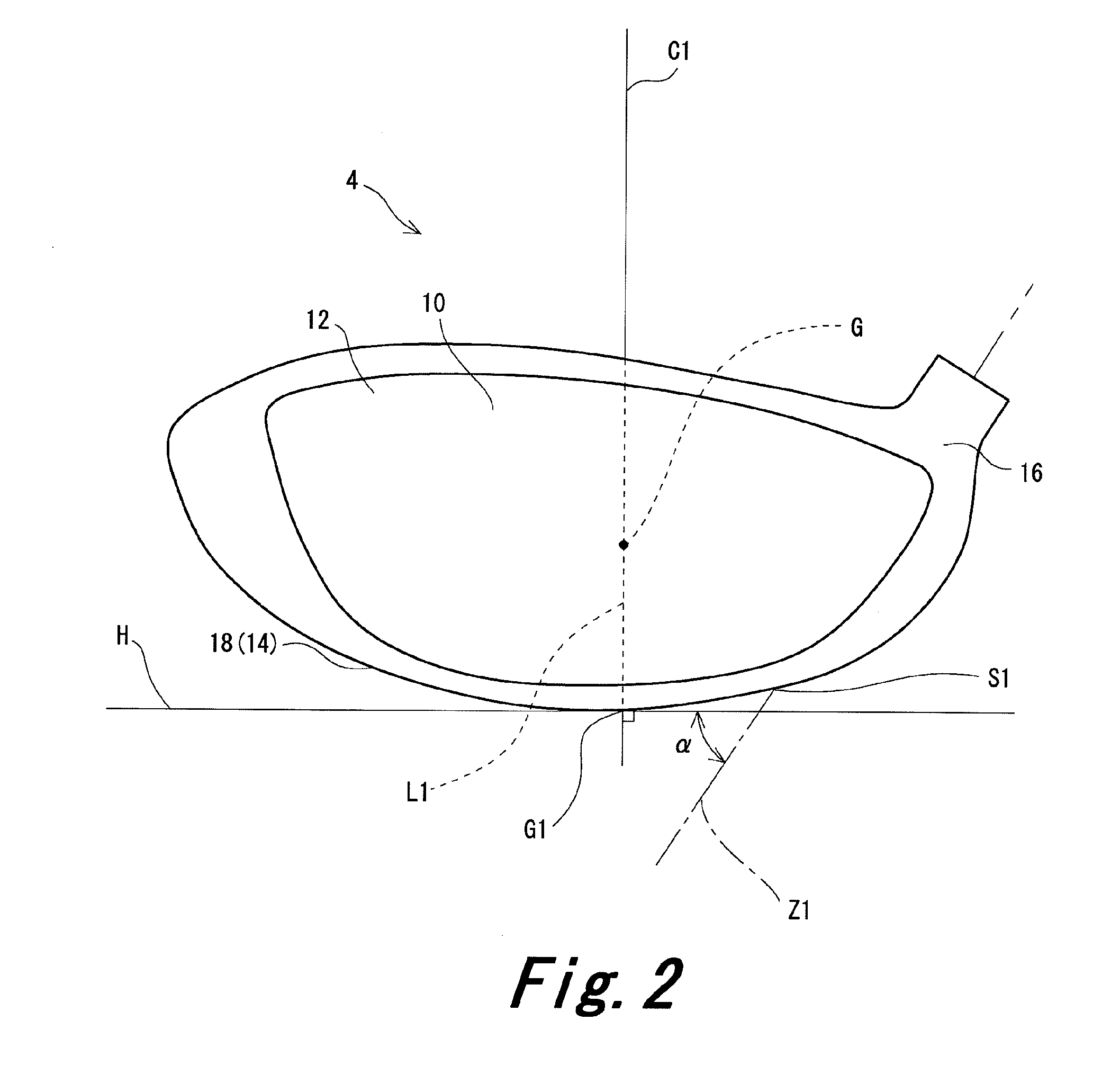
[0135]In example 1, a recess having a weight port existed in a section A2. However, in this example 1, the angle θ (two-section contact lie angle θ) exi...
example 2
[0136]A golf club according to example 2 was obtained in the same manner as in example 1 except that a recess was added to a section A5.
[0137]In example 2, a recess having a weight port existed in a section A2. Furthermore, a recess existed in a section A5. However, in this example 2, the angle θ (two-section contact lie angle θ) existed so that a straight line belonging to a section A1 and a straight line belonging to the section A2 were brought into contact with the ground plane. The range of the angle θ was the same as that of example 1.
example 3
[0142]The whole section A5 in comparative example 1 was the recess. A golf club of example 3 was obtained in the same manner as in comparative example 1 except for above.
[0143]In example 3, a section A1 and a section A2 could be simultaneously grounded by the recess of the section A5. That is, in this example 2, the angle θ (two-section contact lie angle θ) existed so that a point belonging to the section A1 and a point belonging to the section A2 were brought into contact with the ground plane. The range of the angle θ was the same as that of example 1.
[0144]The easiness of addressing for these examples and comparative examples was evaluated.
[Evaluation]
[0145]Ten average golf players used each club to evaluate the easiness of addressing. Of the ten golf players, the number of the golf players estimated that it is easy to address the club of example 1 was 7 players; the number of example 2 was 7 players, the number of example 3 was 6 players, the number of comparative example 1 was ...
PUM
 Abstract
Description
Claims
Application Information