Image forming apparatus and method capable of improving fixing quality

a technology of image forming and fixing quality, which is applied in the direction of electrographic process equipment, instruments, optics, etc., can solve the problems of paper jamming and poor fixing quality

Active Publication Date: 2013-04-25
RICOH KK
View PDF22 Cites 24 Cited by
  • Summary
  • Abstract
  • Description
  • Claims
  • Application Information

AI Technical Summary

Benefits of technology

[0007]The exemplary embodiments described herein can provide at least an image forming apparatus comprising multiple image making units that are able to layer toner images on a recording medium, where a fixing characteristic value of a toner of the top layer is a value that makes it possible to fix the toner of the top layer on the recording medium at a lower temperature than the toners of the other layers. In other words, the toner of the top of the layer has a lower fixing temperature than the other toners.

Problems solved by technology

This technology decreases problems like fixing offset, poor fixing quality or a paper jam caused by adhesion of a paper to a fixing member.

Method used


Image

  • Image forming apparatus and method capable of improving fixing quality
  • Image forming apparatus and method capable of improving fixing quality
  • Image forming apparatus and method capable of improving fixing quality

Examples


first embodiment

The First Embodiment

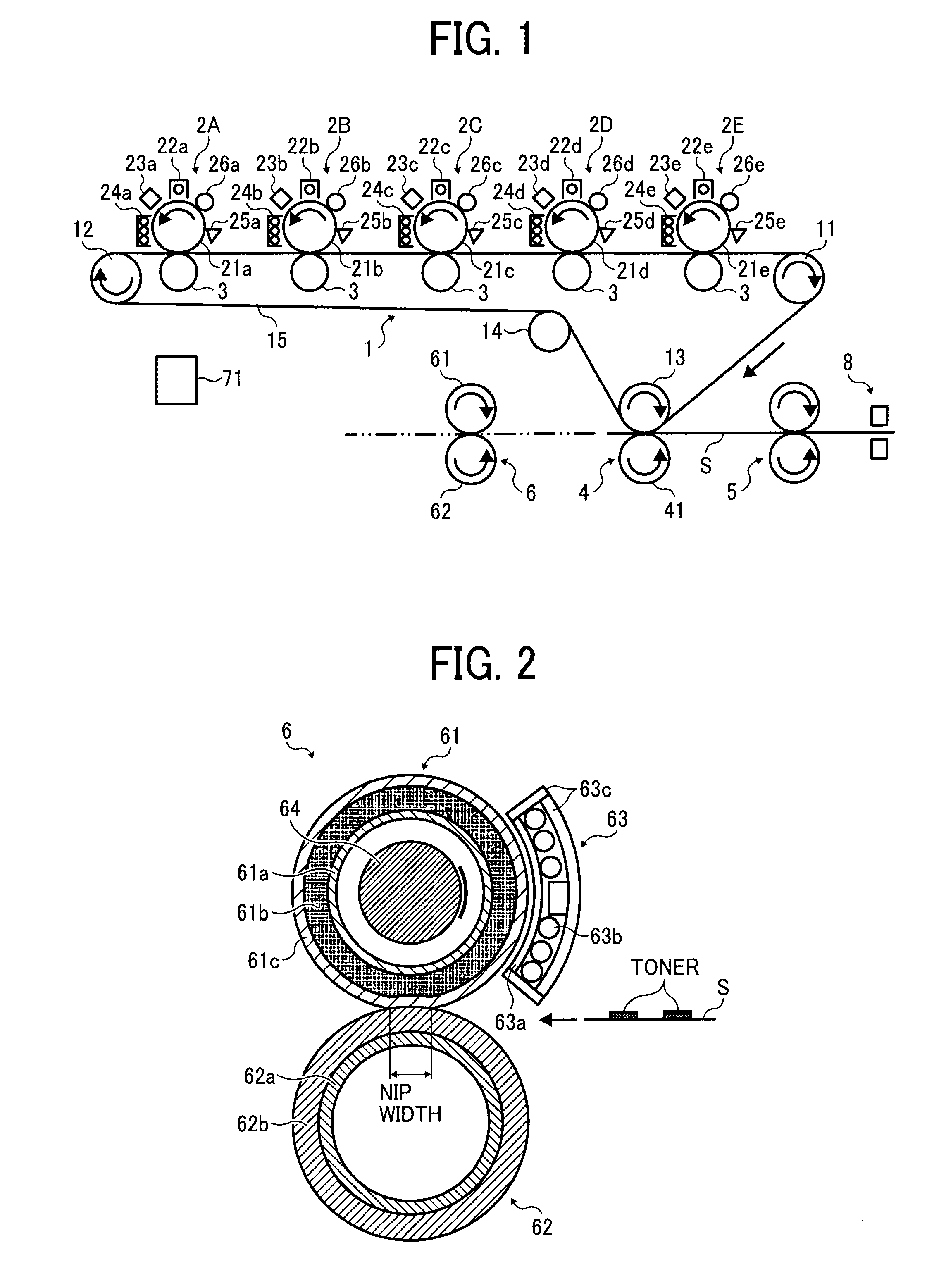
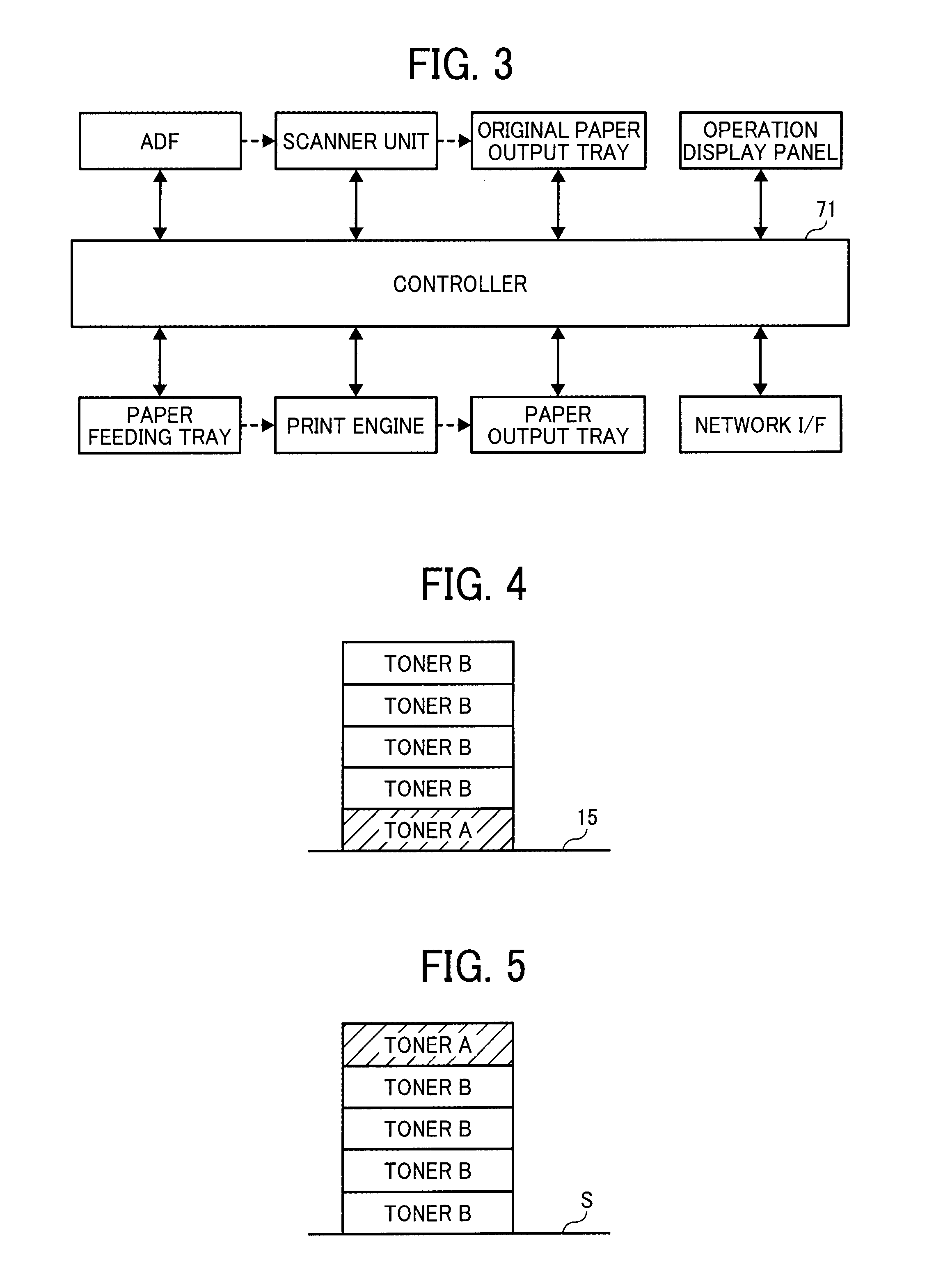
[0041]An image forming apparatus in the first embodiment has an image making system shown in FIG. 1 including a developer. The image making system has an intermediate transfer belt unit 1, image forming unit 2A-2E, a first transfer unit 3, a second transfer unit 4, a sheet feeding unit 5, a fixing unit 6 and a controller 71. An image forming apparatus can also have a feeding paper tray, an output paper tray, an ADF (Auto Document Feeder), a scanner unit, a document output paper tray, a display panel and other units.

[0042]The intermediate transfer belt unit 1 has a driving roller 11, a driven roller 12 located a predetermined distance from the driving roller 11 in a lateral direction, a second transfer opposing roller 13 located below both rollers and near the driving roller 11, a tension roller 14 located between the driven roller 12 and the second transfer opposing roller 13, and a intermediate transfer belt 15 set in these rollers. Driving roller 11 rotates the...

second embodiment

The Second Embodiment

[0092]As explained in the first embodiment, by making the toner thermal property enable a lower fixing temperature than the other toners, a better fixing state can be achieved.

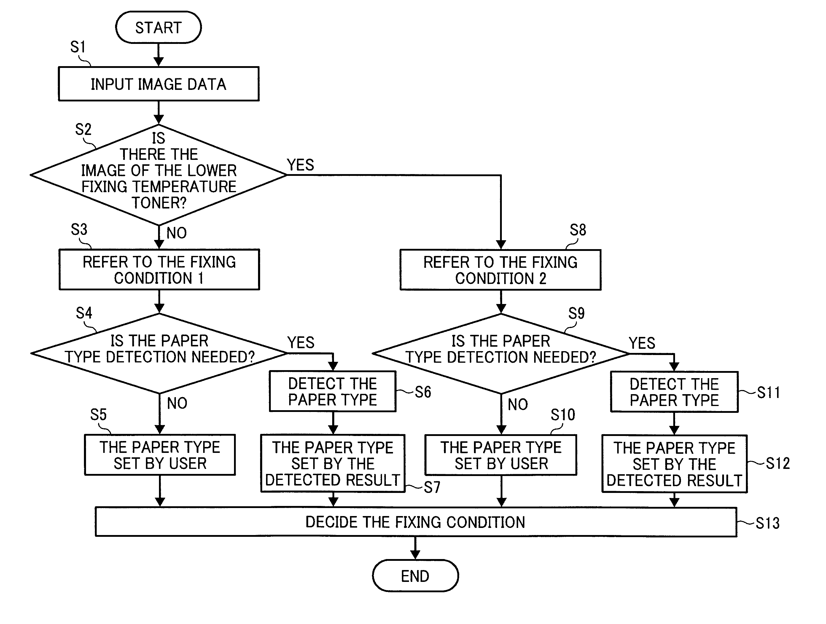
[0093]However, types of papers (the difference of basis weight, the difference of ream weight, the difference of paper kinds like PPC paper, matte paper, art paper, coat paper, etc., hereinafter called paper type) affects fixing state. For example, thick paper is difficult to achieve good fixing quality with, compared to thin papers, because thick paper absorbs heat from the fixing roller and decreases the fixing temperature.

[0094]So, the image forming apparatus in the second embodiment makes it possible to change the fixing condition to accommodate each paper type. The explanation of the same structure with the first embodiment is omitted in the following explanation. In the explanation, basis weight means the paper weight per 1 m2. And ream weight means the weight of 1000 papers of a pre...

third embodiment

The Third Embodiment

[0107]The image forming apparatus in the second embodiment changes the fixing condition in each paper. The image forming apparatus in the third embodiment changes the lower fixing temperature toner quantity at the top of the layers including no lower fixing temperature toner in each paper type by using the area coverage modulation method. The area coverage modulation method is the method for making gray scale by changing the area ratio of the area adhered toner and no toner area. In the third embodiment, a half tone dot image is used. The explanation of the same structure with the first and the second embodiment is omitted. Further, clear toner is used as the lower fixing temperature toner in this embodiment.

[0108]The image forming apparatus in the third embodiment has a controller 73 and the paper type detecting unit 8 discussed in the second embodiment. The controller 73 shown in FIG. 12 has an information storage unit 731, an image data processing unit 732, an...


PUM


Abstract

In an image forming apparatus, multiple toners are superimposed, formed and layered, on a recording medium and a toner image is made. The toner that superimposed lastly on the recording medium, that is, a top layer of toner, has a toner fixing characteristic value that causes the top layer of toner to be fixed on the recording medium by lower temperature than one or all of the other multiple toners. This provides for a better fixing quality.

Description

CROSS-REFERENCE TO RELATED APPLICATIONS[0001]This patent application is based on and claims priority pursuant to 35 U.S.C. §119 to Japanese Patent Application Nos. 2011-230354, filed on Oct. 20, 2011, in the Japanese Patent Office, the entire content of which is hereby incorporated by reference herein.BACKGROUND[0002]1. Technological Field[0003]The exemplary embodiments described herein relate to an image forming apparatus and an image forming method.[0004]2. Description of the Related Art[0005]Conventionally, image forming apparatuses in electrophotography that use process color toners such as cyan, magenta, yellow and black set a limit of total toner quantity per unit image area (or pixel) to prevent problems like fixing offset, poor fixing quality or a paper jam caused by adhesion of a paper to a fixing member. Such technology is described in Japanese Patent Publication No. 2004-77807 and No. 2004-191853.[0006]This technology decreases problems like fixing offset, poor fixing qua...

Claims


Application Information

Patent Timeline
Patent Type & Authority Applications(United States)
IPC IPC(8): G03G15/00G03G15/20G03G15/08
CPCG03G15/205G03G15/6585G03G15/2064G03G2215/00751G03G15/2078G03G2215/00738G03G15/5029G03G15/2039
Inventor KASAI, TADASHIKOBAYASHI, SHINYASONOHARA, YOSHIHIROTERAO, MASAKAZUSAKURAI, YOICHI
Owner RICOH KK
Why Eureka
Try Eureka