Calendar mechanism and timepiece having the same

a technology of a timepiece and a mechanism, applied in the direction of mechanical clocks, instruments, horology, etc., can solve the problems of high energy consumption, high cost, and high cost, and achieve the effect of preventing the increase of frictional load and avoiding excessive complexity

Inactive Publication Date: 2013-07-04
SEIKO INSTR INC
View PDF6 Cites 1 Cited by
  • Summary
  • Abstract
  • Description
  • Claims
  • Application Information

AI Technical Summary

Benefits of technology

[0013]To achieve the above object, according to the present invention, there is provided a calendar mechanism comprising: a month cam equipped with a cam surface distinguishing between a long month having 31 days and a short month having 30 days or less and adapted to make one rotation a year; a date indicator equipped with a date wheel and a month end tooth; a date indicator driving wheel equipped with a date finger adapted to make one rotation every 24 hours and engaged with the date wheel of the date indicator to rotate the date indicator; and an operating lever structure whose proximal portion is friction-engaged with an offset shaft so as to be capable of rotating around the offset shaft offset with respect to the rotation center of the date indicator driving wheel and which is equipped with a first distal end portion constituting a cam follower engaged with the month cam and a second distal end portion constituting a short month end feeding finger engaged with the month end tooth of the date indicator to effect additional date feeding by one day with respect to the date indicator at the end of a short month.
[0014]In the calendar mechanism according to the present invention, “the proximal portion of the operating lever structure is friction-engaged with an offset shaft so as to be capable of rotating around the offset shaft offset with respect to the rotation center of the date indicator driving wheel,” so that the operating lever structure rotates together with the date indicator driving wheel; “the operating lever structure is equipped with a first distal end portion constituting a cam follower engaged with the month cam,” so that the cam follower is pressed against the month cam when the operating lever structure rotates together with the date indicator driving wheel; “the proximal portion of the operating lever structure is friction-engaged with the offset shaft of the date indicator driving wheel,” so that when the cam follower is pressed against the month cam, the operating lever structure makes relative rotation with respect to the offset shaft; “the operating lever structure is equipp

Problems solved by technology

However, in this case, positional control in the radial direction of the date indicator driving wheel is to be performed on the rigid finger, so that the rigid finger constituting the month end feeding finger structure is retained so as to be capable of translation in the radial direction of the date indicator driving wheel within, the range of the diameter of the date indicator driving wheel with respect to the rotation center of the date indicator driving wheel, and is caused to translate in the radial direction by the month cam in a short month, which means a request for a rather complicated structure and for high dimensional precision is inevitable for the space that can be occupied by the finger

Method used


Image

  • Calendar mechanism and timepiece having the same
  • Calendar mechanism and timepiece having the same
  • Calendar mechanism and timepiece having the same

Examples


embodiment

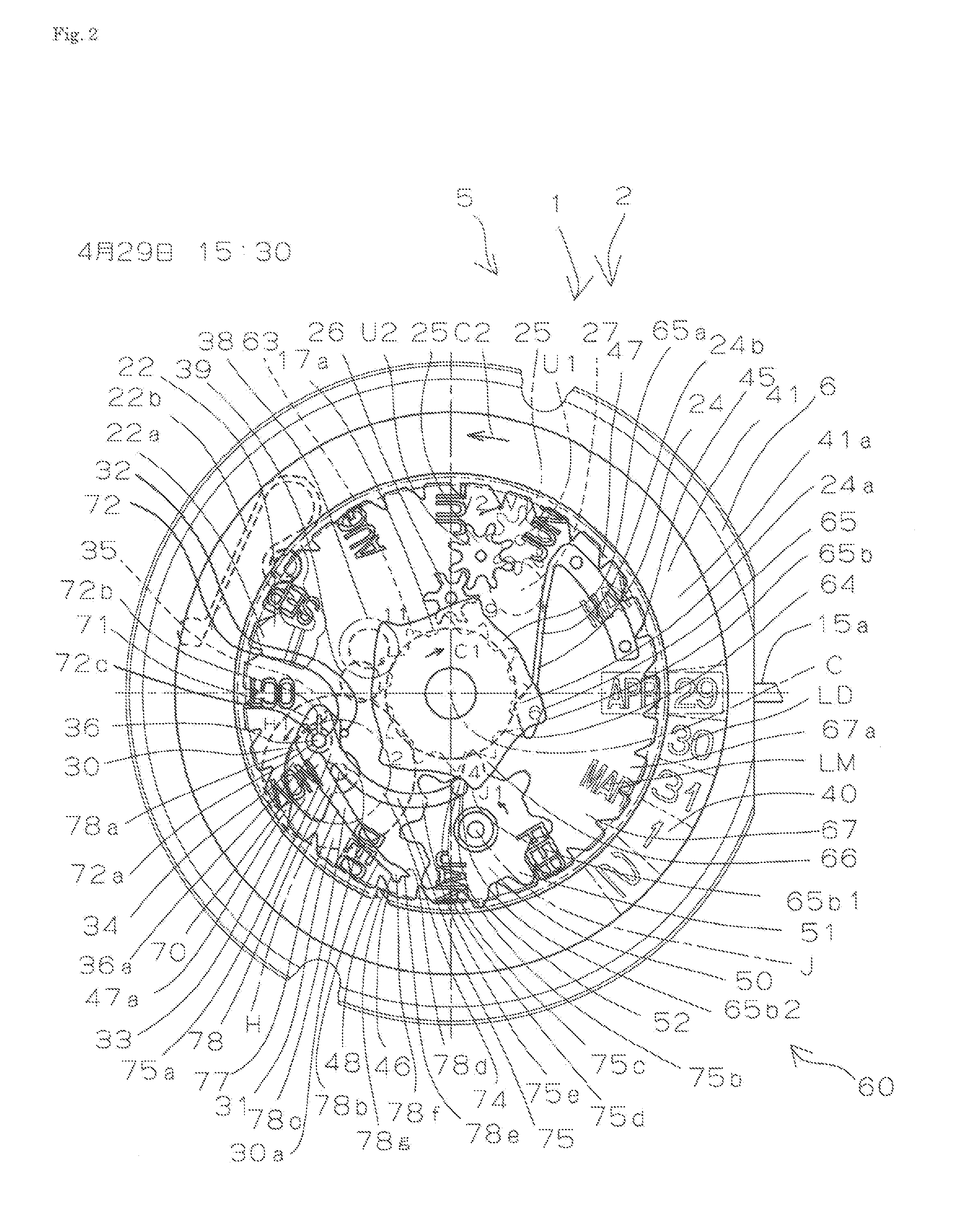
[0052]FIGS. 1 through 24 show a timepiece 2 equipped with an auto calendar mechanism 1 as a calendar mechanism according to a preferred embodiment of the present invention.

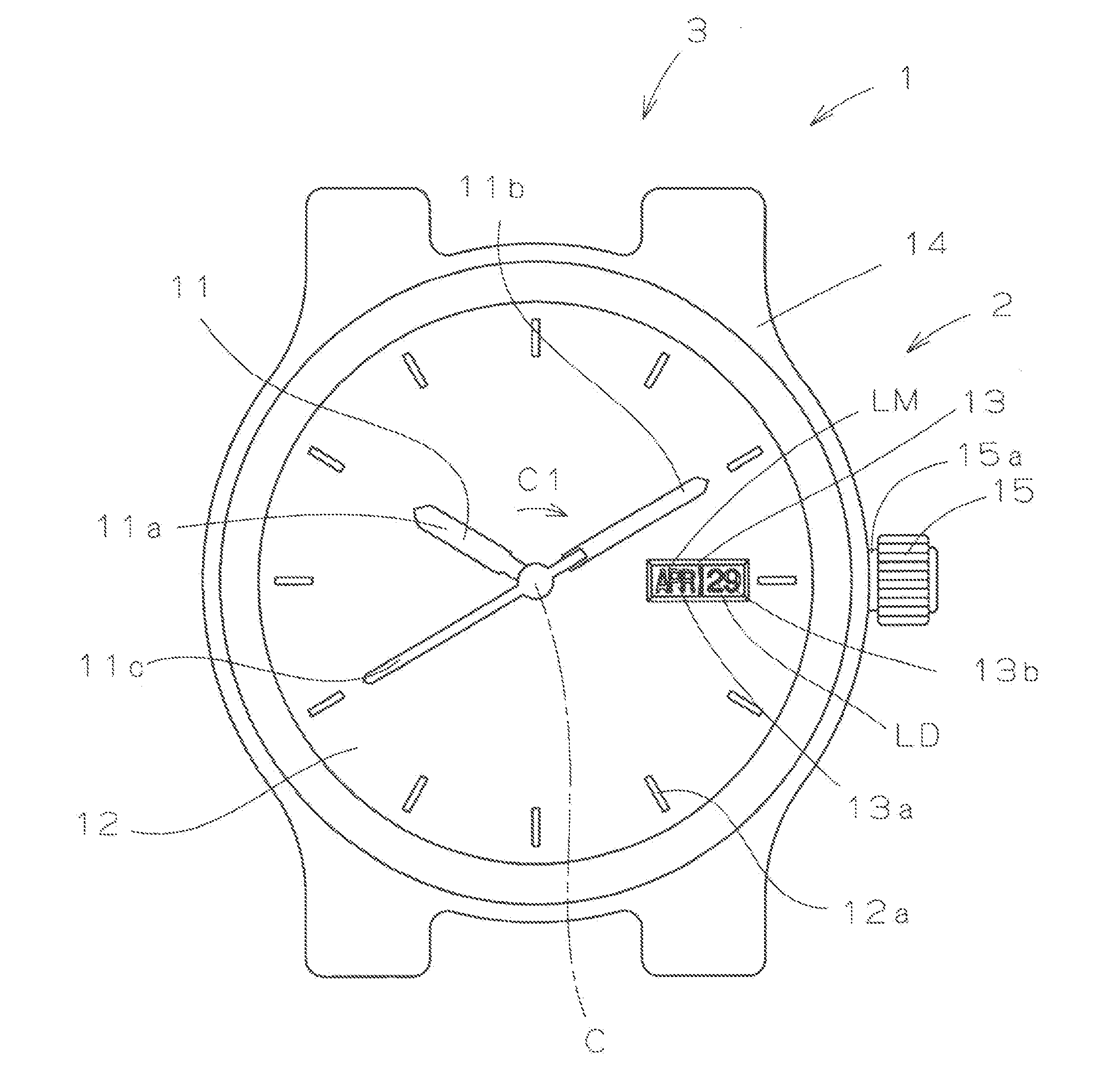
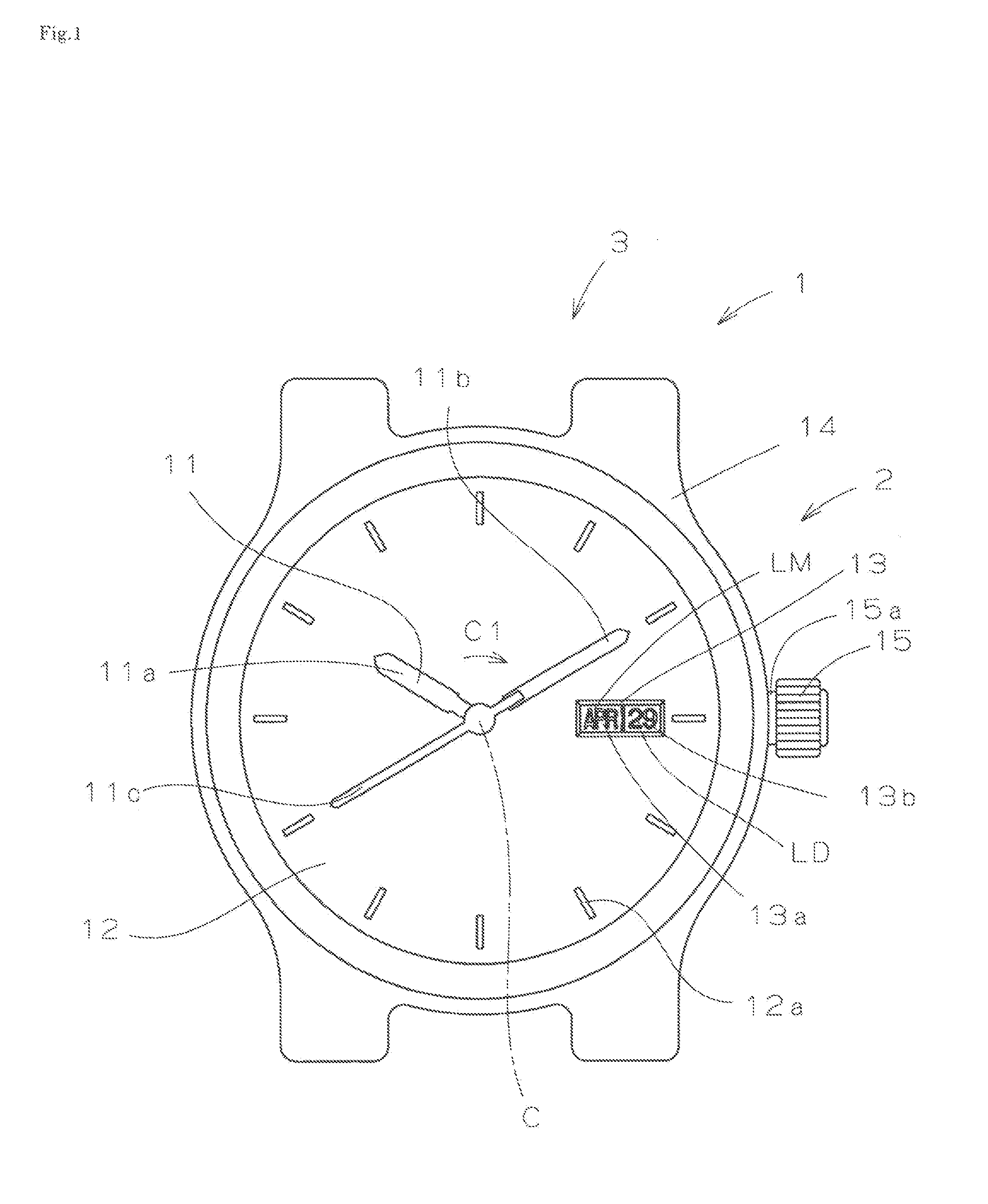
[0053]The timepiece 2 has an outward appearance 3 as shown in FIG. 1. That is, the timepiece 2 is equipped with time indicating hands 11 consisting of an hour hand 11a, a minute hand 11b, and a second hand 11c, which are rotatable clockwise C1 around a center axis C. A dial 12 of the timepiece 2 has set characters 12a indicating time positions, and a month / date display window 13 equipped with a month indicating area 13a and a date indicating area 13b. Numeral 14 indicates a timepiece case, and numeral 15 indicates a crown mounted to a winding stem 15a.

[0054]In the example shown in the sectional views of FIGS. 3 and 4, an hour wheel 16a to the forward end of which the hour hand 11a is mounted, a minute wheel 16b to the forward end of which the minute hand 11b is mounted, and a second wheel a pinion 16c to the forw...


PUM


Abstract

A calendar mechanism of a timepiece includes a month cam having a cam surface distinguishing between a long month (31 days) and a short month (30 days or less) and makes one rotation a year. A date indicator driving wheel has a date finger that makes one rotation every 24 hours and engages with a date wheel of a date indicator to rotate the date indicator. An operating lever structure has a proximal portion friction-engaged with an offset shaft to rotate around the offset shaft offset with respect to the rotation center of the date indicator driving wheel. The operating lever structure has a first distal end portion engaged with the month cam and a second distal end portion engaged with a month end tooth of the date indicator to effect additional date feeding by one day with respect to the date indicator at the end of a short month.

Description

BACKGROUND OF THE INVENTION[0001]1. Field of the Invention[0002]The present invention relates to a calendar mechanism, and a timepiece having the same.[0003]2. Description of the Related Art[0004]Regarding a calendar mechanism, various techniques are known as techniques for forming a so-called auto calendar mechanism which per forme month feeding for a longer month (a month which has 31 days and which is also referred to as a long month in this specification) and for a shorter month (a month which has not more than 30 days and which is also referred to as a short month in this specification) in different manners.[0005]In an auto calendar mechanism, from the month end (30th day) of a shorter month other than February to the first day of a longer month, date feeding is effected by extra one day as an additional date feeding to perform date feeding by two days; in this connection, various mechanisms have been proposed; in particular, there has been proposed provision of a data indicato...

Claims


Application Information

Patent Timeline
IPC IPC(8): G04B19/253
CPCG04B19/253G04B19/2536
Inventor SUZUKI, SHIGEO
Owner SEIKO INSTR INC
Why Eureka
Try Eureka