Armature and motor

a technology of armature and motor, applied in the field of armature, can solve the problems of reducing the likelihood that any the first lower decreased thickness portion will be damaged, and achieve the effects of improving the strength of the first lower decreased thickness portion, improving precision, and significantly improving the strength of the first upper decreased thickness portion

Inactive Publication Date: 2013-08-01
NIDEC CORP
View PDF6 Cites 24 Cited by
  • Summary
  • Abstract
  • Description
  • Claims
  • Application Information

AI Technical Summary

Benefits of technology

[0007]Preferred embodiments of the present invention provide a structure of an insulator including a pair of resin members fitted to each other that prevents both damage of each resin member and a decreased precision in molding of each resin member.
[0009]According to the above preferred embodiment of the present invention, the strength of the first upper decreased thickness portion is significantly improved by the first upper rib. In addition, the strength of the first lower decreased thickness portion is significantly improved by the first lower rib. This reduces the likelihood that any of the first upper decreased thickness portion and the first lower decreased thickness portion will be damaged when the upper and lower resin members are fitted to each other. Moreover, channels through which a molten resin flows in a molding process are expanded by spaces arranged to permit molding of the ribs. This preferably improves precision with which each of the decreased thickness portions is molded.

Problems solved by technology

This reduces the likelihood that any of the first upper decreased thickness portion and the first lower decreased thickness portion will be damaged when the upper and lower resin members are fitted to each other.

Method used


Image

  • Armature and motor
  • Armature and motor
  • Armature and motor

Examples


first preferred embodiment

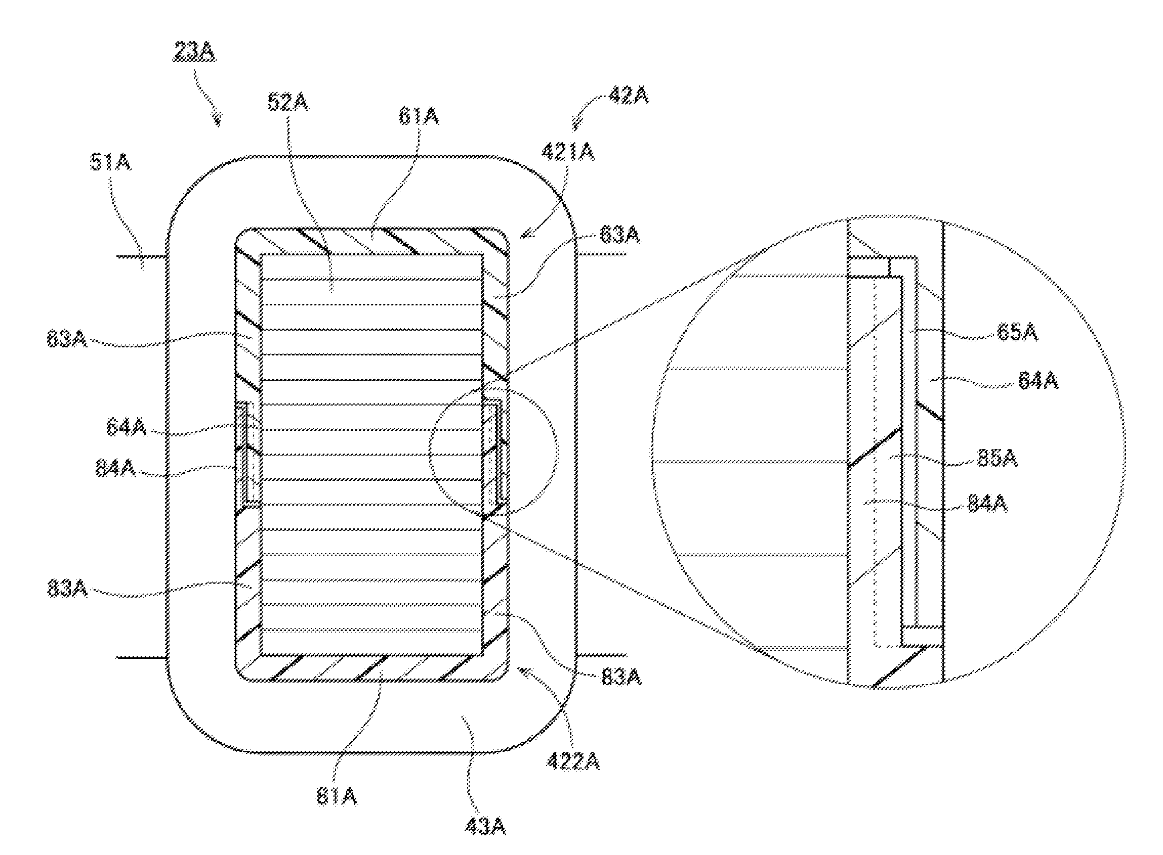
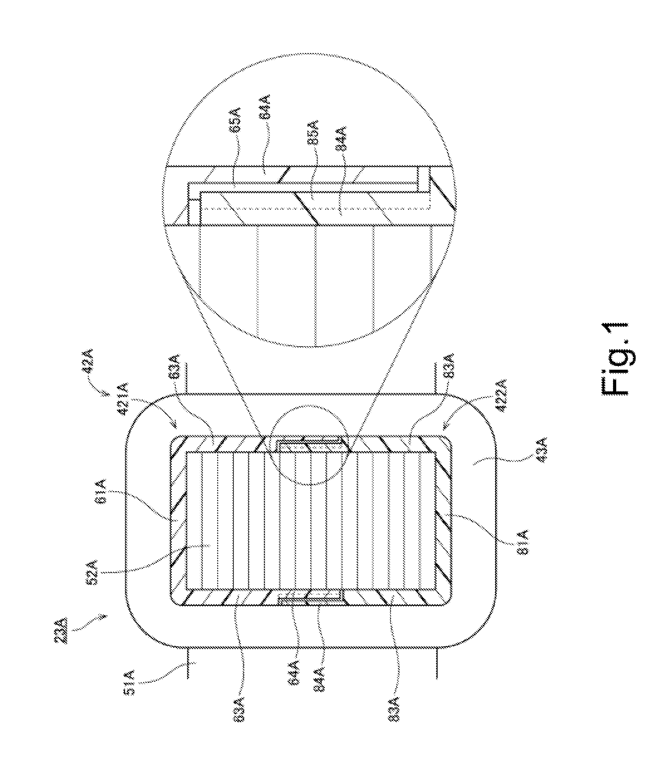
[0022]FIG. 1 is a cross-sectional view of an armature 23A according to a first preferred embodiment of the present invention taken along a plane perpendicular to a direction in which one of teeth 52A extends. Referring to FIG. 1, the armature 23A preferably includes a core back 51A, the teeth 52A, insulators 42A, and coils 43A.

[0023]The core back 51A preferably has an annular shape. The teeth 52A are arranged to extend radially inward from the core back 51A. Note that the teeth 52A may alternatively be arranged to extend radially outward from the core back 51A. An upper surface, a lower surface, and circumferential side surfaces of each of the teeth 52A are preferably covered by a separate one of the insulators 42A. Each of the coils 43A is preferably defined by, for example, a conducting wire wound around a separate one of the insulators 42A.

[0024]Each insulator 42A preferably includes an upper resin member 421A and a lower resin member 422A.

[0025]The upper resin member 421A prefer...

second preferred embodiment

[0031]Next, a second preferred embodiment of the present invention will now be described below.

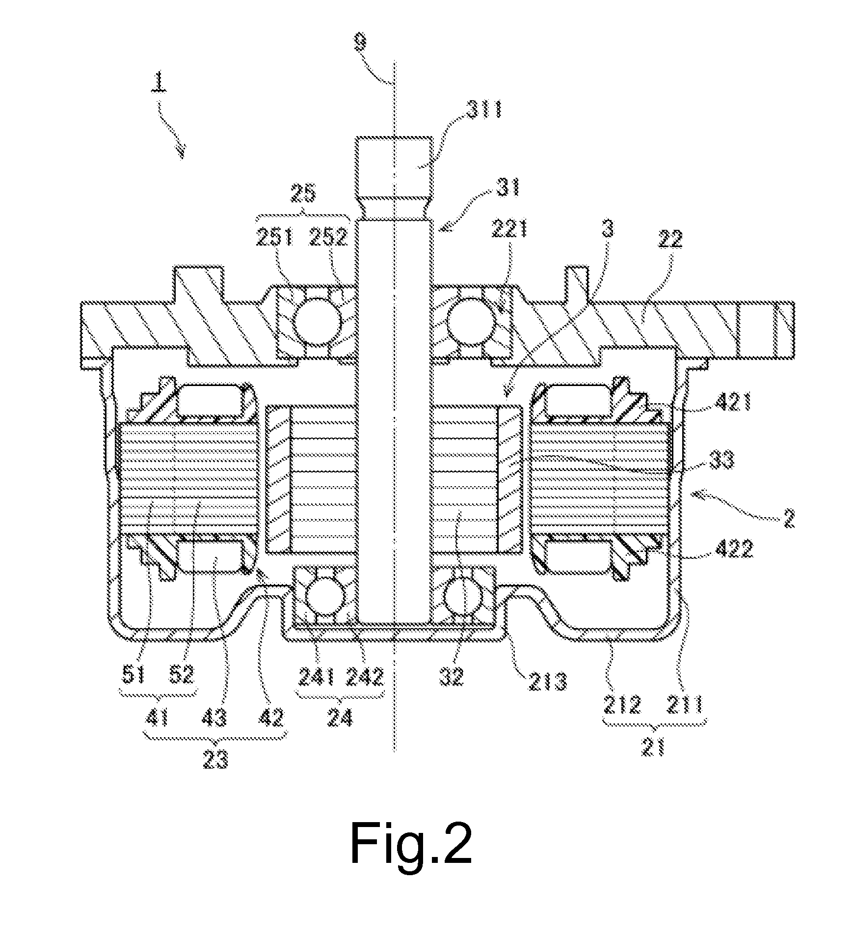
[0032]FIG. 2 is a vertical cross-sectional view of a motor 1 according to a second preferred embodiment of the present invention. The motor 1 according to the second preferred embodiment is preferably, for example, installed in an automobile and used to produce a driving force for a power steering device. Note, however, that motors according to other preferred embodiments of the present invention may be used for applications other than power steering. For example, a motor according to a preferred embodiment of the present invention may be used as a driving source for another portion of the automobile, e.g., an engine cooling fan. Further, motors according to preferred embodiments of the present invention may be installed in household electrical appliances, office automation appliances, medical appliance, and so on, and may be used to produce a variety of driving forces, for example.

[0033]R...


PUM


Abstract

An insulator of an armature includes an upper resin member and a lower resin member. Each of the upper and lower resin members includes decreased thickness portions. Axial positions of the decreased thickness portions of the upper and lower resin members are arranged to overlap at least partially with each other. Each of the upper and lower resin members further includes a rib arranged to project from a corresponding one of the decreased thickness portions. The rib improves the strength of the corresponding decreased thickness portion and reduces the likelihood that any of the decreased thickness portions of the upper and lower resin members will be damaged when the two members are fitted to each other.

Description

BACKGROUND OF THE INVENTION[0001]1. Field of the Invention[0002]The present invention relates to an armature and more specifically to an armature for use in a motor.[0003]2. Description of the Related Art[0004]JP-A 2003-079080 describes a stator including a stator core, coils, and insulating members, as an example of a conventional armature used in a motor. In the stator described in this publication, each insulating member, which is tubular in shape, is arranged between a separate one of the coils and a corresponding one of magnetic pole teeth of the stator core (see, e.g., claim 1 of JP-A 2003-079080). In addition, each insulating member described in JP-A 2003-079080 is made up of two insulating member pieces joined to each other (see, e.g., claim 3 of JP-A 2003-079080). Moreover, the two insulating member pieces described in JP-A 2003-079080 are fitted to each other such that end portions of the insulating member pieces overlap with each other (see paragraph [0024] and FIG. 3 of ...

Claims


Application Information

Patent Timeline
Patent Type & Authority Applications(United States)
IPC IPC(8): H02K3/34
CPCH02K3/345H02K2203/12H02K3/522H02K3/30H02K3/46H02K3/325
Inventor YOKOGAWA, TOMOYOSHI
Owner NIDEC CORP
Why Eureka
Try Eureka