Power spring configurations for a fastening device

a technology of power springs and fastening devices, which is applied in the direction of manufacturing tools, nailing tools, stapling tools, etc., can solve the problems of coils spreading apart and causing unfavorable inner housing wall pressing and scraping

Active Publication Date: 2013-09-05
WORKTOOLS
View PDF8 Cites 13 Cited by
  • Summary
  • Abstract
  • Description
  • Claims
  • Application Information

AI Technical Summary

Benefits of technology

[0012]In a preferred embodiment, a tab of the striker presses atop the latch. The power spring extends through both the striker and the latch, but is not restrained by the latch. A resulting advantage is the spring length, as defined by the position of the front tip, can vary without affecting the release action. By contrast, a latch engagement to the spring tip can be sensitive to the positio

Problems solved by technology

The coils spread apart to undesirably press and scrape th

Method used


Image

  • Power spring configurations for a fastening device
  • Power spring configurations for a fastening device
  • Power spring configurations for a fastening device

Examples


Embodiment Construction

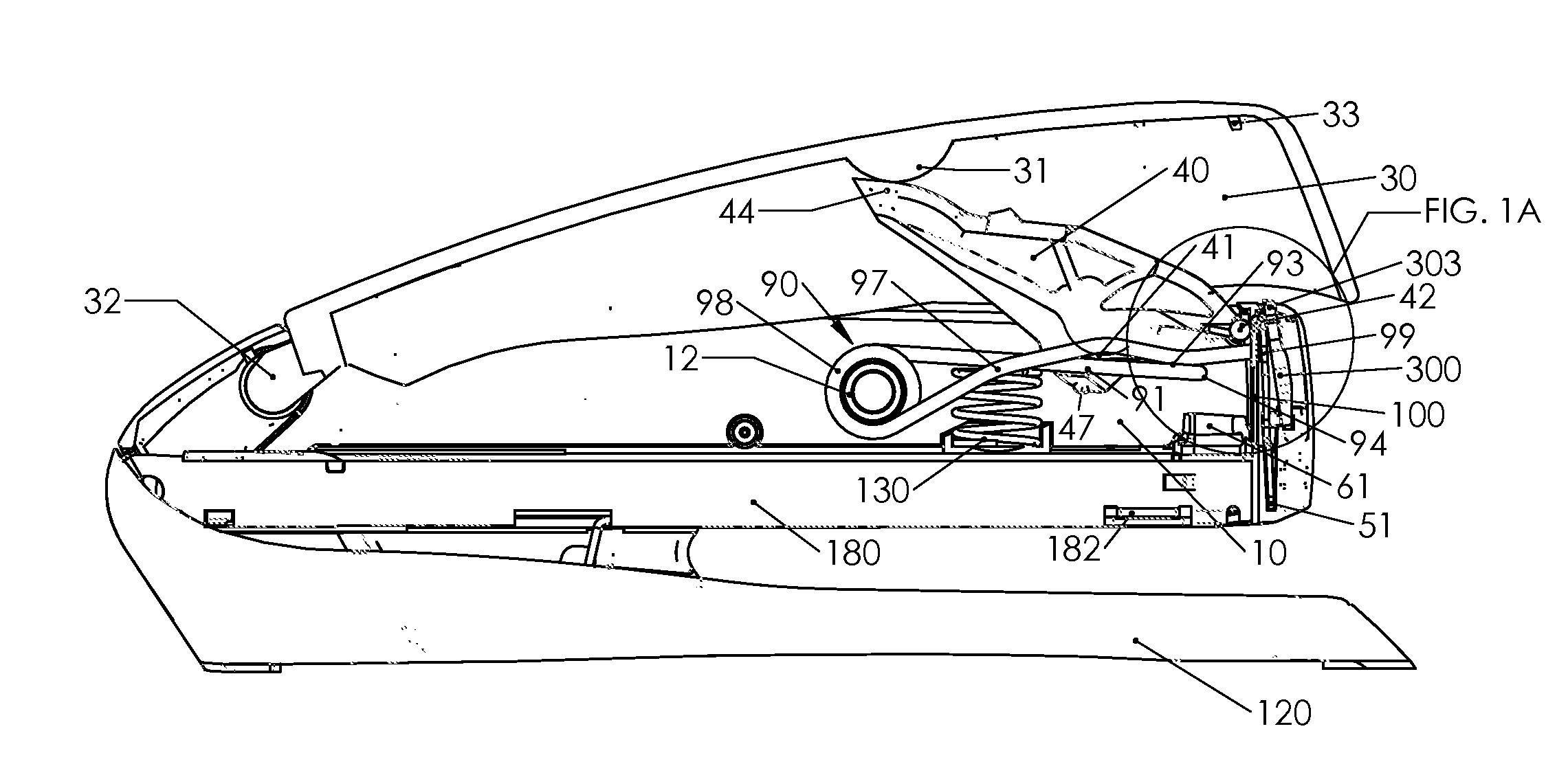
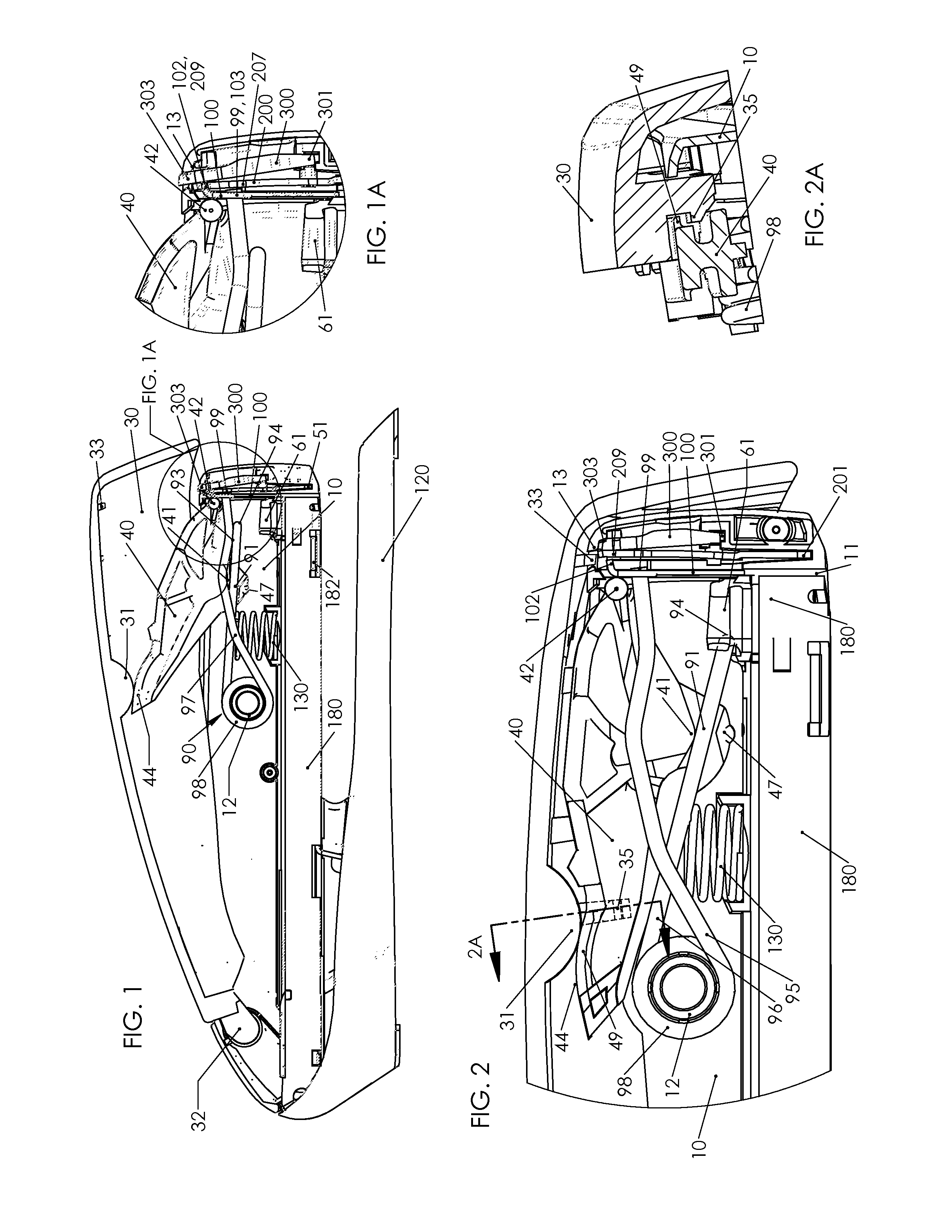
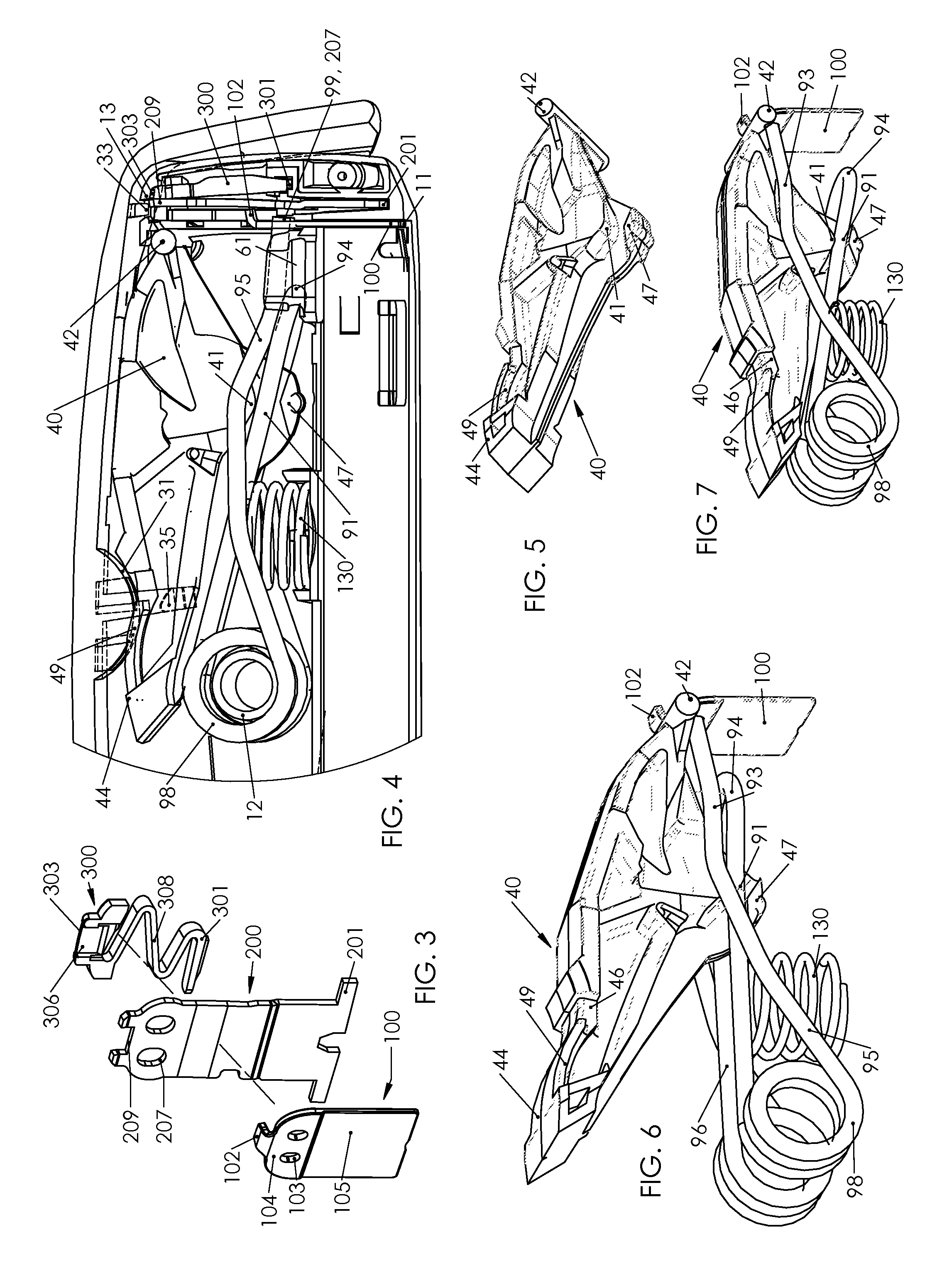
[0036]FIGS. 1 to 12 show a standard duty desktop stapler including a preferred embodiment of the power spring of the present invention. For example, preferred embodiment power spring 90 includes coil 98 with terminal arm 95 and loop arm 96 extending forward from the coil, as seen in FIG. 9. Identical opposed elements of the double torsion spring may be addressed herein equivalently and in the singular for brevity. It is understood that there are two of each such element, or two pairs, in the preferred embodiment.

[0037]The present invention is directed to a spring energized fastening device. In a desktop stapler form seen in FIG. 1, base 120 or its equivalent structure is optionally included. Track 180 is at a bottom of housing 10 and guides staples or other fasteners (not shown) to striker 100 at the front of the stapler.

[0038]In the power spring 90, the respective arms 95 and 96 include a free condition as shown in FIG. 11. This is a shape of the power spring 90 as it is manufactur...


PUM


Abstract

Power spring configurations for a spring energized fastening device includes a compact double torsion power spring and two opposed compact single torsion springs. Simplified structures to hold the springs in a stable pre-loaded position are disclosed. Each coil has forward extending arms including an angled portion and forward vertically coincident portions. The double torsion spring has a self-locking crossing geometry to hold a pre-loaded rest position. The opposed two springs have a bridge and a mandrel to hold the rest position. A lever presses arms of the spring between a striker and the coil including a compact nesting condition. A tab of the striker extends forward to provide a release edge and a positioning torque bias upon the striker.

Description

BACKGROUND[0001]The present invention relates to spring energized fastening tools. More precisely, the present invention relates to improvements to the spring and release of a spring-actuated stapling device.[0002]Spring powered staplers and staple guns operate by driving a striker with a power spring. The striker ejects a staple by impact blow. In a desktop stapler, the staple is ejected into an anvil of a pivotally attached base. In a staple gun, the fastener is normally installed directly into a work surface. Two general principles are used in either type device. In the first design, the striker has an initial position in front of a staple track. The striker is lifted against the force of the power spring to a position above the staple track. The striker is released to impact and eject the staple. This design may be referred to as a “low start” stapler. A second design uses a “high start” position. That is, the striker has an initial position above the staples loaded on the stapl...

Claims


Application Information

Patent Timeline
IPC IPC(8): B25C5/06
CPCB25C5/0235B25C5/0228B25C5/02B25C5/11
Inventor MARKS, JOEL S.
Owner WORKTOOLS
Why Eureka
Try Eureka