Power assisting Transmission System of Power Assisting Bike

Active Publication Date: 2014-03-06
UNIQUE PRODS & DESIGN
View PDF4 Cites 7 Cited by
  • Summary
  • Abstract
  • Description
  • Claims
  • Application Information

AI Technical Summary

Benefits of technology

The objective of this patent is to create a power-assisting bike that can move forward and backward, or have a braking effect by backpedaling.

Problems solved by technology

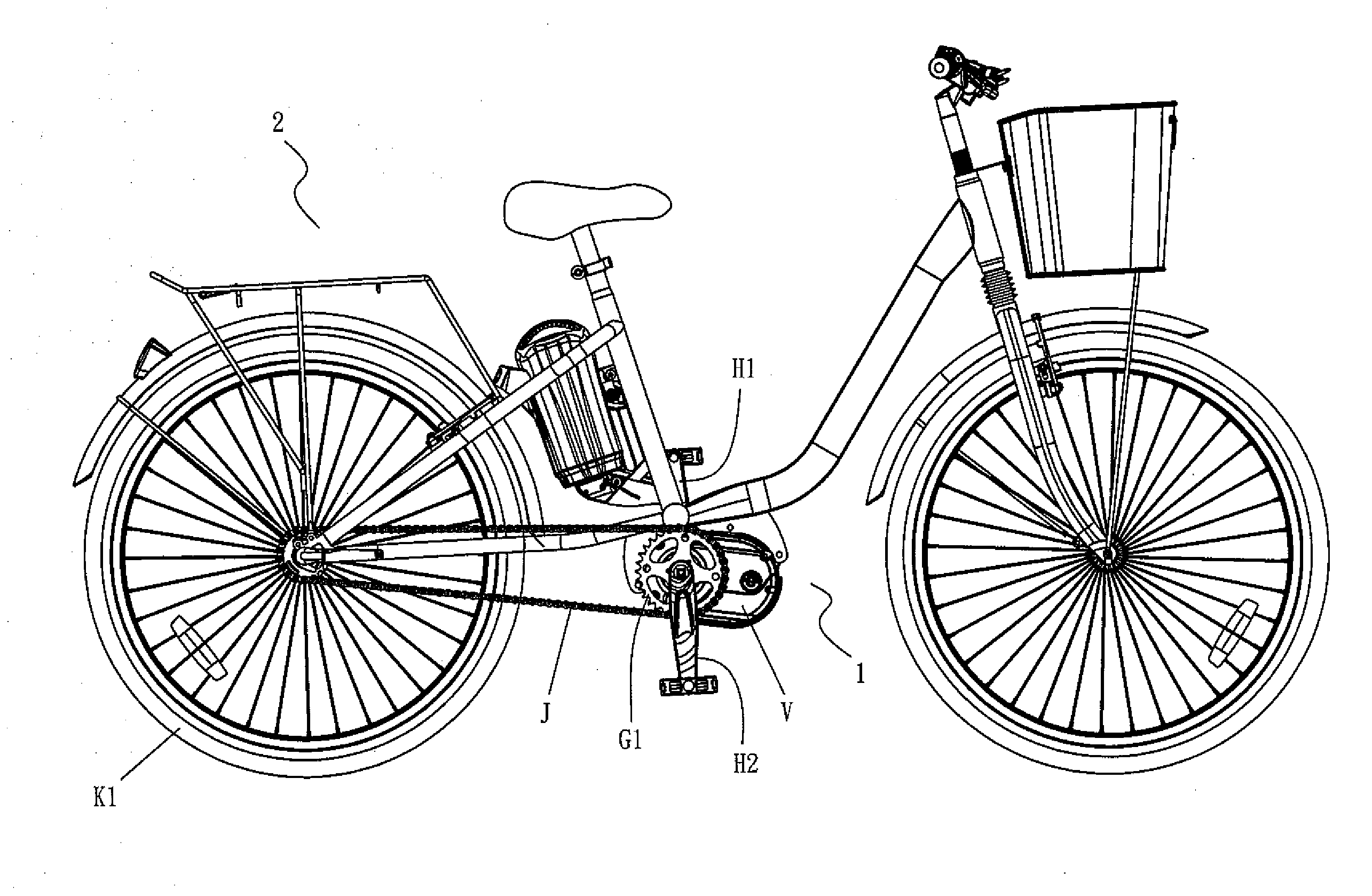
Therefore, when a conventional power assisting bike is pedaling in a backward direction manually in an idle pedaling status, a chain gear G1 cannot be driven to rotate, so that the power assisting bike does not have any backward pedaling function and it obviously requires improvements.

Method used


Image

  • Power assisting Transmission System of Power Assisting Bike
  • Power assisting Transmission System of Power Assisting Bike
  • Power assisting Transmission System of Power Assisting Bike

Examples


Embodiment Construction

[0020]The objectives, technical characteristics, measures, effects and advantages of the present invention will become apparent with the detailed description of preferred embodiment accompanied with the illustration of related drawings as follows.

[0021]With reference to FIGS. 1 to 3 for a transmission system of a preferred embodiment of the present invention, the transmission system 1 comprises:[0022]a first transmission shaft A, having a left end A1 and a right end A2 coupled to pedal cranks H1, H2 respectively, and the pedal cranks H1, H2 being disposed on both left and right sides of the power assisting bike 2 respectively, such that the first transmission shaft A is driven when the pedal cranks H1, H2 are pedaled and driven by an external force; a left-handed screw gear C, installed at the left end A1 of the first transmission shaft A and operated synchronously with the first transmission shaft A, wherein when the external force is provided for a forward pedaling, the first tran...


PUM


Abstract

A power assisting transmission system of a power assisting bike is provided for driving a gear of the transmission system to produce a lateral force in forward and backward pedaling and detect an axial displacement of a sliding gear in the transmission system to output a voltage signal to control motive power for driving a motor, so as to achieve forward and backward transmissions or a back pedaling brake effect.

Description

BACKGROUND OF THE INVENTION[0001]1. Field of the Invention[0002]The present invention relates to a power assisting transmission system of a power assisting bike, and more particularly to the power assisting transmission system of a power assisting bike capable of achieving forward and backward transmissions or a back pedaling brake effect by forward and backward pedaling.[0003]2. Description of the Related Art[0004]As disclosed in U.S. Pat. No. 6,595,072 entitled “Sensor of the pedaling force of a power assisting bike”, a transmission system of the power assisting bike comprises one or more pairs of screw gears, wherein the screw gear is driven by a pedaling force to rotate in situ, and the other screw gear is engaged by the opposite screw gear installed on a shaft and driven to move horizontally in an axial direction, and the screw gear has a resilience member installed at an end of the screw gear and the resilience member and the shaft of the screw gear have an annular magnet move...

Claims


Application Information

Patent Timeline
IPC IPC(8): F16H37/06
CPCB62M6/55Y10T74/19023Y10T74/19051
InventorLIAO, GORDON
OwnerUNIQUE PRODS & DESIGN