Printing apparatus and printing method

Active Publication Date: 2015-02-26
CANON KK
View PDF2 Cites 4 Cited by
  • Summary
  • Abstract
  • Description
  • Claims
  • Application Information

AI Technical Summary

Benefits of technology

[0007]The present invention provides a printing apparatus and a printing method that s

Problems solved by technology

According to this printing method, there are some cases where a streak-shaped density unevenness (hereinafter, called “a connecting streak”) is generated in a connecting section between the predetermined printing areas due to an error of a conveyance amou

Method used


Image

  • Printing apparatus and printing method
  • Printing apparatus and printing method
  • Printing apparatus and printing method

Examples


first embodiment

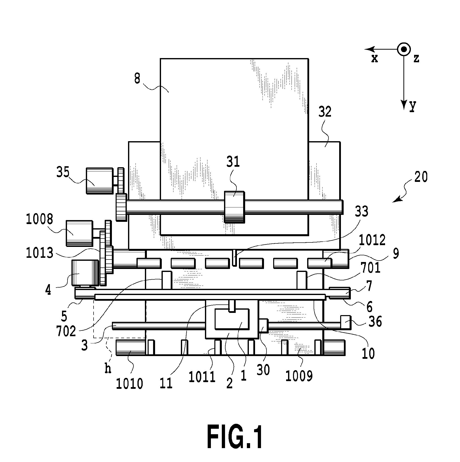
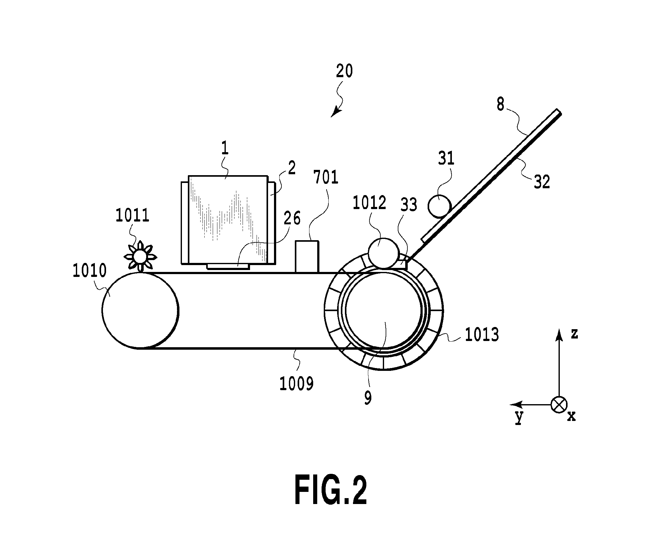
[0048]FIG. 1 is a schematic top view showing the internal configuration of a printing apparatus 20. FIG. 2 is a schematic side view showing the internal configuration of the printing apparatus 20. As shown in these figures, the printing apparatus 20 is provided with a sheet feeder 32, a conveying belt 1009, a carriage 2, measuring devices 701, 702, and the like.

[0049]Print mediums 8 are loaded on the sheet feeder 32. A pickup roller 31 is arranged in a position having the print medium 8 between the sheet feeder 32 and the pickup roller 31. The pickup roller 31 is rotated by a supply motor 35 to separate the print mediums 8 loaded on the sheet feeder 32 one by one, and the separated medium 8 is supplied in a conveying / sub scan direction (y direction in the figure). A sheet detector 33 shown in FIG. 1 detects the print medium 8 supplied from the sheet feeder 32.

[0050]The conveying belt 1009 is a sheet-shaped carrier wound around a drive roller 9 and a driven roller 1010 rotated by rot...

second embodiment

[0139]In the first embodiment, the first raster area in the end is used to correct the connecting streak. However, in a case where the oblique motion amount is large, there are some cases where even if the correction is made using one raster area in the end, the connecting streak cannot be appropriately corrected.

[0140]Therefore in the present embodiment, it is selected whether one raster area in the end is used for correction or a plurality of raster areas including one raster area in the end are used for correction, depending on the oblique motion amount. Therefore in the present embodiment, masks for making the correction using one raster area in the end and masks for making the correction using a plurality of raster areas including one raster area in the end are prepared. In addition, tables for selecting these masks each are stored in a predetermined memory. The other configuration is the same as in the first embodiment, and therefore the explanation is omitted herein.

[0141]FIG...

third embodiment

[0148]An explanation will be made of a method in which correction is not made in the central part of the print medium and correction is made in both ends thereof across the central part in the main scan direction. The other configuration is the same as in the first embodiment, and the explanation is omitted herein.

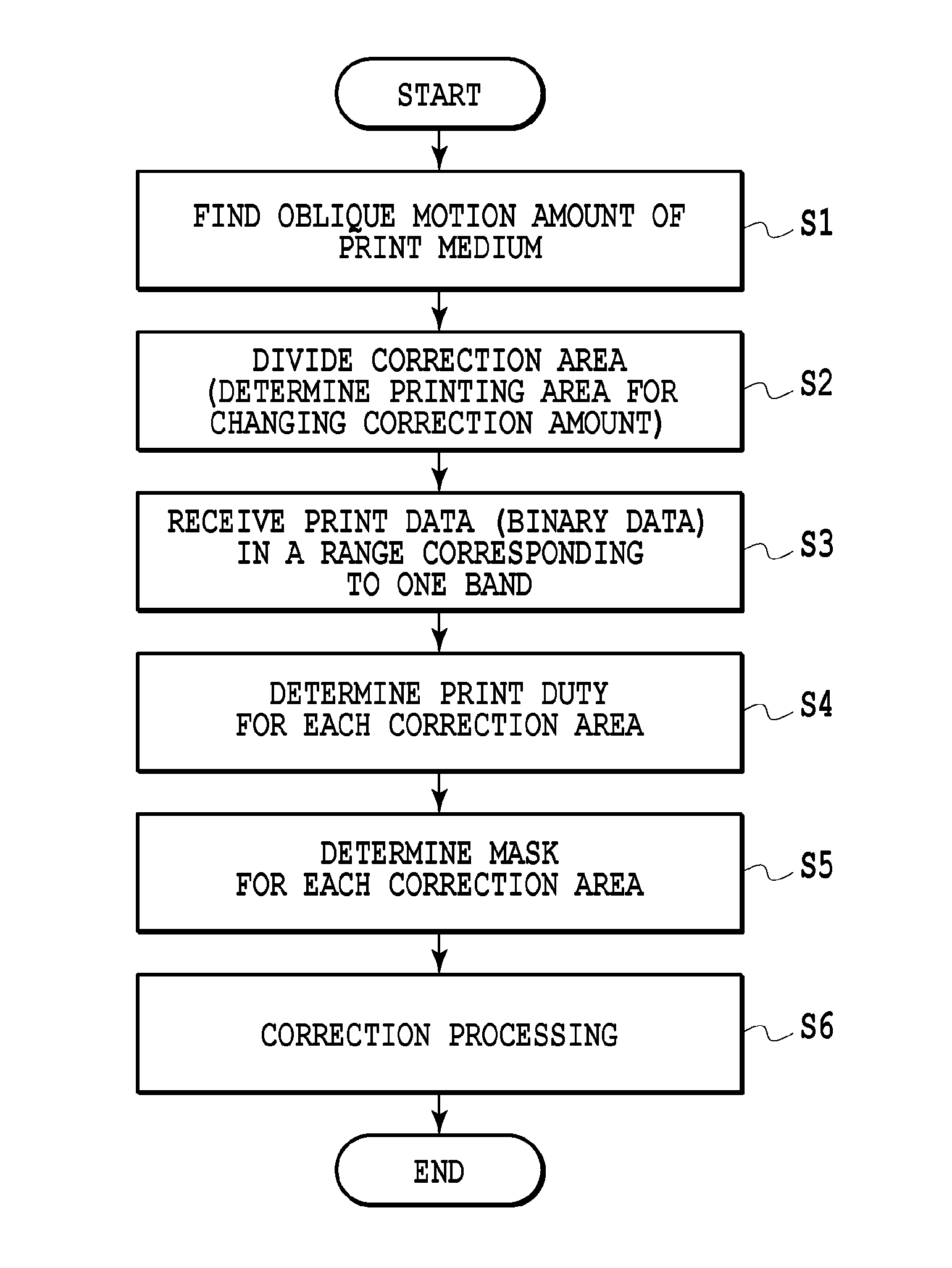
[0149]FIG. 19 is a flowchart explaining correction processing in the present embodiment. As shown in this figure, in the present embodiment, in order that a connecting streak due to a conveyance error is not generated in the center of the print medium 8, in step S7 the conveyance amount of the print medium 8 is adjusted before starting the correction processing. This adjustment of the conveyance amount of the print medium 8 is performed by controlling rotation of the conveying motor 1008. In a case where the conveyance amount of the pint medium 8 is longer than a desired conveyance amount, the print medium 8 is wound back, and in a case where the conveyance amount of the p...


PUM


Abstract

A printing apparatus includes: a print head for applying ink on a print medium; a print control unit configured to control the print head; a conveying unit; an obtaining unit configured to obtain information regarding a conveyance error of conveyance of the print medium in a conveying direction crossing a predetermined direction by the conveying unit with respect to each of a plurality of areas of the print medium that are in positions different from each other in the predetermined direction; and an adjusting unit configured to divide a predetermined area of the print medium in accordance with a conveyance error amount indicated by the information in each of the plurality of areas obtained by the obtaining unit into a plurality of correction areas, and to adjust the amount of ink to be applied onto each of the plurality of correction areas lining up in the predetermined direction.

Description

BACKGROUND OF THE INVENTION[0001]1. Field of the Invention[0002]The present invention relates to a printing apparatus and a printing method, and in particular, to a printing apparatus and a printing method that suppresses generation of density unevenness caused by an oblique motion of a print medium.[0003]2. Description of the Related Art[0004]There is known a method of printing an image on a print medium by scanning a predetermined printing area (band) by one time or plural times (one pass or multi-pass) while conveying the print medium in a printing apparatus. According to this printing method, there are some cases where a streak-shaped density unevenness (hereinafter, called “a connecting streak”) is generated in a connecting section between the predetermined printing areas due to an error of a conveyance amount of the print medium or the like.[0005]For suppressing generation of this connecting streak, Japanese Patent Laid-Open No. 2007-190861 discloses an image forming apparatus...

Claims


Application Information

Patent Timeline
IPC IPC(8): B41J13/00
CPCB41J13/0009B41J2/2135B41J11/0095B41J19/142
Inventor WADA, SATOSHIMARUMOTO, YOSHITOMO
Owner CANON KK
Why Eureka
Try Eureka