Stator of rotary electric machine

a technology of rotating electric machines and stabilizers, which is applied in the direction of dynamo-electric components, dynamo-electric machines, structural associations, etc., can solve the problems of easy damage to the insulation coating films of the coils, and damage to the insulation of the coils between the coils having high inter-phase potential differences, so as to achieve the effect of effectively preventing damage to the insulation of the coils and simplifying construction

Active Publication Date: 2016-03-31
TOYOTA JIDOSHA KK
View PDF5 Cites 11 Cited by
  • Summary
  • Abstract
  • Description
  • Claims
  • Application Information

AI Technical Summary

Benefits of technology

[0012]In the stator of the rotary electric machine as constructed above, the phase coils of three phases are wound around the teeth of the stator core, and the inter-phase distance ensuring member is provided such that the inter-phase distance ensuring member, in a slot among the plurality of slots in which one phase coil directly connected to the power terminal and another phase coil directly connected to the neutral point are adjacently disposed, is disposed in a gap via which the two coils are adjacent. The inter-phase potential difference between the one phase coil directly connected to the power terminal and the another phase coil directly connected to the neutral point assumes the maximum value among the phase coils of three phases. The inter-phase distance ensuring member is disposed between the one phase coil and the another phase coil, so that damage to insulatio

Problems solved by technology

An insulation coating film is provided on the coils, nevertheless if the insulation coating film is thermally degraded, the insulation will be easily damaged.
If the potential difference between the coils of different phases, i.e. the inter-phase potential difference, is high, t

Method used


Image

  • Stator of rotary electric machine
  • Stator of rotary electric machine
  • Stator of rotary electric machine

Examples


Embodiment Construction

[0020]Hereinafter, embodiments of the invention will be described in detail by using the accompanying drawings. A stator of a rotary electric machine mounted on a vehicle will be described below, but this is merely an example for descriptive illustration, and it can also be used in other applications than being mounted on a vehicle. The number of teeth, the number of slots, the number of turns of the coils, and so on, as described below, are only presented for descriptive illustration, and can be varied as appropriate according to the specifications of the stator of the rotary electric machine. Hereinafter, like elements will be denoted by like reference characters throughout the drawings, and redundant descriptions thereof will be omitted.

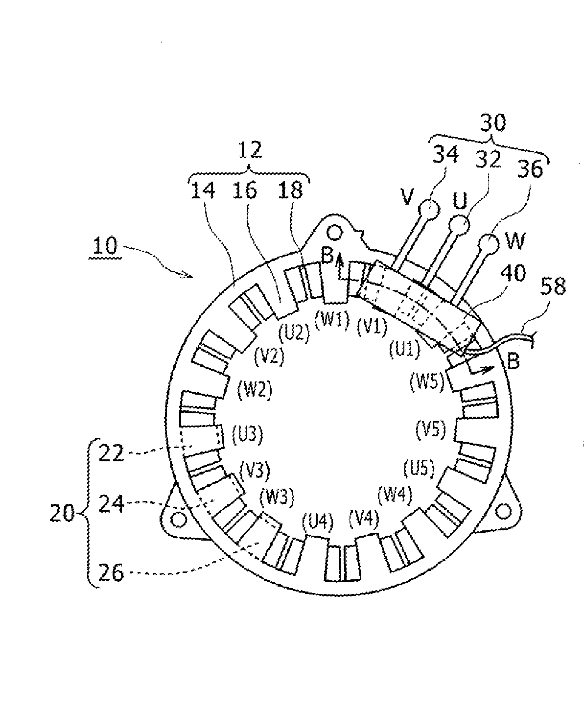
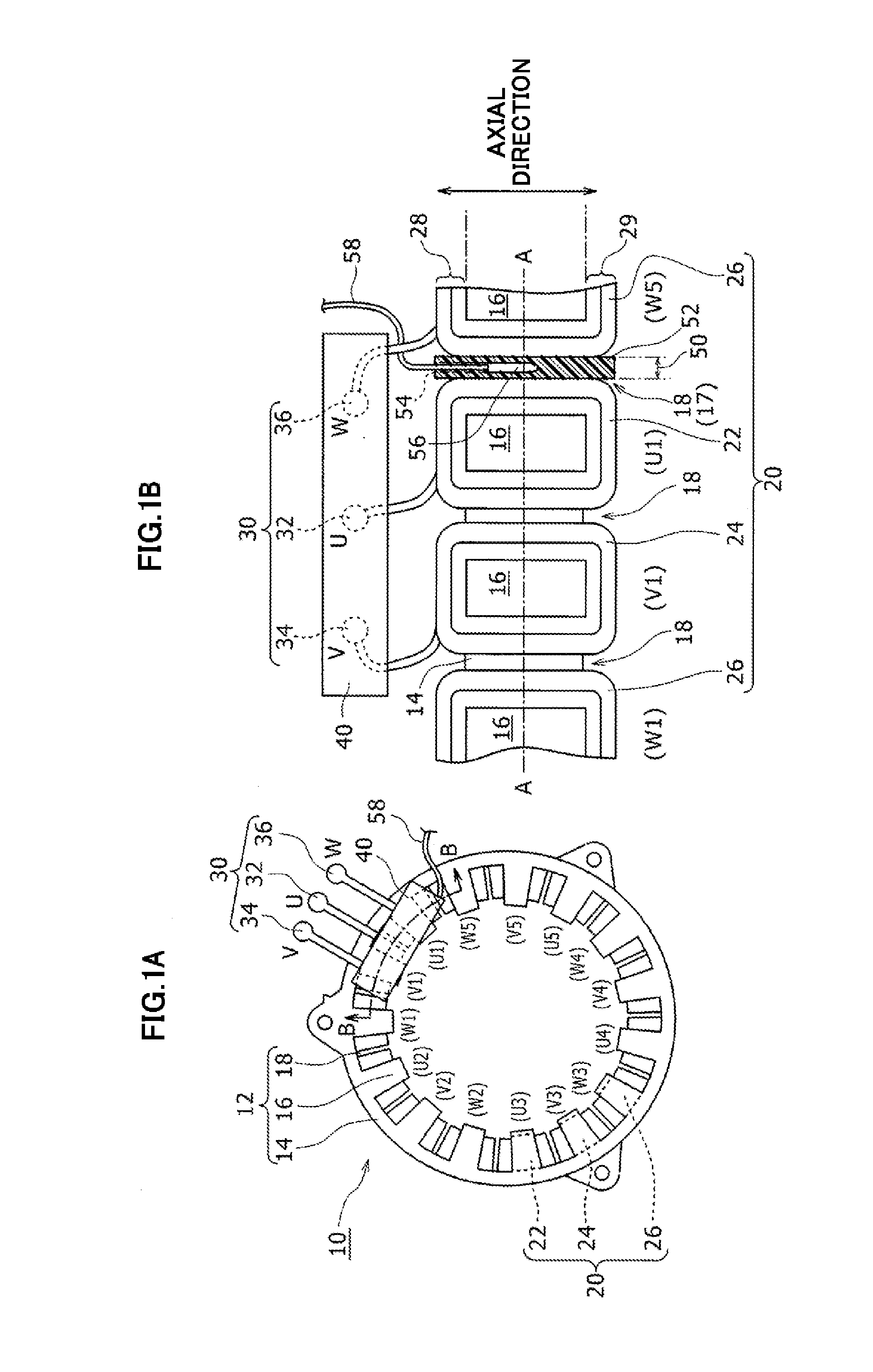
[0021]FIG. 1A and FIG. 1B is a structural diagram of a stator 10 of a rotary electric machine. Below, the stator 10 of the rotary electric machine will be referred to as “stator 10” unless otherwise specified. FIG. 1A is a view showing a section o...


PUM


Abstract

A stator of a three-phase driving type rotary electric machine has phase coils wound around teeth of a stator core. In a specific slot among a plurality of slots of the stator core in which one phase coil directly connected to a power terminal and another phase coil directly connected to a neutral point are adjacently disposed, an inter-phase distance ensuring member is disposed in a gap via which the two phase coils are adjacent, and a temperature sensor is inserted into an insertion hole provided in the inter-phase distance ensuring member.

Description

INCORPORATION BY REFERENCE[0001]The disclosure of Japanese Patent Application No. 2014-199783 filed on Sep. 30, 2014 including the specification, drawings and abstract is incorporated herein by reference in its entirety.BACKGROUND OF THE INVENTION[0002]1. Field of the Invention[0003]The invention relates to a stator of a rotary electric machine, and in particularly, to a stator of a rotary electric machine in one of slots of which coils of different phases are adjacently disposed.[0004]2. Description of Related Art[0005]Coils are provided with a stator of a rotary electric machine. An insulation coating film is provided on the coils, nevertheless if the insulation coating film is thermally degraded, the insulation will be easily damaged. Therefore, a temperature sensor is used in order to detect the temperature of the stator coil.[0006]For example, in Japanese Patent Application Publication No. 2011-254628 (JP 2011-254628A), it is disclosed for a structure for attaching the temperat...

Claims


Application Information

Patent Timeline
IPC IPC(8): H02K3/28H02K3/34H02K3/48H02K11/00
CPCH02K3/28H02K3/34H02K3/48H02K11/0047H02K11/25H02K2213/03
Inventor HOSHINA, HIROSHI
Owner TOYOTA JIDOSHA KK
Why Eureka
Try Eureka